Editor’s Note: As many Light Metal Age articles and items have noted, the friction stir welding (FSW) process, which joins aluminum components in the solid state, has been applied throughout the world in various industries that produce products for transportation, B&C, and industrial and consumer sectors.
The November 2020 selection of patents covered a wide range over the last decade. By comparison, the patents herewith cover just the FSW patents granted in the U.S. in the last year. As the teachings in several of these patents indicate, the choice of FSW over traditional fusion welding methods was made to not only improve strength and ductility, reduce residual stresses, and improve microstructure in the weld and heat affected zones, but also to make use of the capability of FSW to join dissimilar aluminum alloys and even aluminum alloys to dissimilar metals with widely different melting temperatures, such as steel and copper. The industries making use of FSW of aluminum range from aerospace to earthly industrial and consumer products across the world.
— Joseph C. Benedyk, Editor
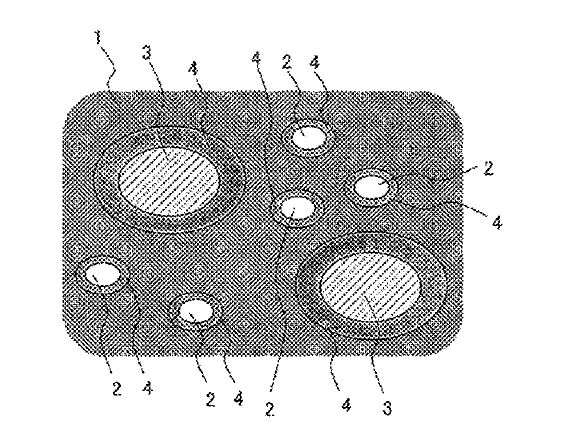
US10933726 — BATTERY HOLDER FOR A VEHICLE — Benteler Automobiltechnik GmbH (Germany) — The disclosure comprises a battery holder for receiving at least one electric battery in a vehicle that includes a hollow chamber profile made by extruding an aluminum alloy with a hollow chamber that is defined by a base wall and a cover wall, where the electric battery is configured for placement on the cover wall. The battery holder also includes a heat exchanger structure configured for tempering the electric battery, where the heat exchanger structure is formed within a cover wall section of the cover wall and includes at least one hollow channel that intersperses the cover wall. Multiple hollow chamber profiles of the battery holder and/or the cover, which can comprise a frame circumferentially defining the battery/batteries, can be joined in a fluid-tight manner by friction stir welding.
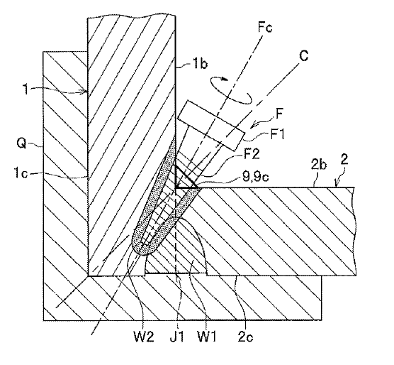
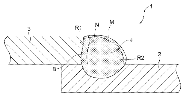
US10906127 — FRICTION STIR WELDING METHOD — Nippon Light Metal Company, Ltd. (Japan) — The present invention provides a friction stir welding method for joining two metal members having faces to be butted in different shapes from each other by a rotary tool having a stirring pin, including steps of: butting in which one metal member is butted with the other metal member to form a butted portion; buildup welding in which the butted portion is applied with buildup welding along a circumferential direction of the other metal member to cover an inner corner of the metal members by a weld metal; and joining in which the stirring pin in rotation is inserted in the inner corner to carry out friction stirring in the butted portion along the circumferential direction of the other metal member in a state where only the stirring pin is brought in contact with the weld metal and the metal members. The friction stir welding method provided can prevent defective welding due to a shortage of metal. The friction stir welding method welds metal members (1, 2) using a primary joining rotary tool (F) having a stirring pin (F2), and includes steps of: butting in which the metal members (1, 2) are butted with each other at an angle to form a butted portion (J1); buildup welding in which buildup welding is applied along an inner corner of the metal members (1, 2) formed in the butting step to cover the inner corner by a weld metal (M); and inner corner joining in which only the stirring pin (F2) in rotation is inserted in the inner corner to plastically fluidize the weld metal (M) and the metal members (1, 2) for friction stir welding of the butted portion (J1).
US10895277 — WELDED JOINT — UACJ Corporation (Japan) — A welded joint comprising an aluminum-based base material comprising an aluminum alloy or pure aluminum and a copper-based base material comprising a copper alloy or pure copper joined by a weld metal portion is provided. The weld metal portion contains copper in ranges of less than 75% by mass and silicon in ranges of less than 13% by mass and has a higher content of copper and silicon than the aluminum-based base material. According to the present disclosure, a welded joint having high joint strength and having excellent ductility can be provided. This welded joint being able to be applied to, for example, electrodes and bus bars for Li ion batteries, and electrodes, terminals, and wiring for electronic devices and wire harnesses. In addition, application is particularly expected in such wide-ranging fields that the use of a welded joint formed by the joining of different types of metal materials, an aluminum-based and a copper-based base material to each other is needed, for the purpose of promoting weight reduction and the like.
US10894699 — LIGHTWEIGHT CRANE — Stellar Industries, Inc. (USA) — Example embodiments relate to a lightweight crane. In one nonlimiting embodiment the crane is comprised of a telescoping boom having a first boom nested in a second boom which in turn is nested in a third boom. The first, second, and third booms may be made from aluminum to reduce the weight of the crane. The first boom may have a first open section and a second closed section wherein the open section is configured to accommodate a structural member to which an actuator is attached. The first and second booms have lower surfaces with inclined surfaces so that the first boom self-aligns with the second boom and the second boom self-aligns with the third boom. As traditional welding of tempered aluminum may also result in the loss of temper and therefore a weaker heat affected zone around the weld. To reduce those issues the inventors have used friction stir welding (FSW) as an alternative to traditional fusion techniques. FSW has a much smaller heat affected zone and does not create crater cracks or stress concentrations as may be created using traditional welding techniques.

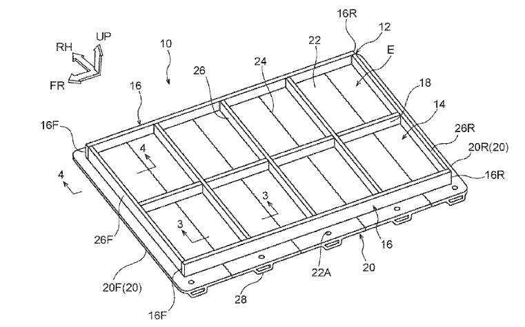
US10894470 — VEHICLE BATTERY-CARRYING FLOOR STRUCTURE — Toyota Jidosha Kabushiki Kaisha (Japan) — A vehicle battery-carrying floor structure made of aluminum extrusions that includes: a bottom plate member that has a plurality of unit members that are arranged in a vehicle body forward and rearward direction and that are joined by joining opposing joint portions, each unit member having a flat plate portion that extends in a vehicle width direction and that has the joint portions formed at an end portion facing the vehicle body forward direction and at an end portion facing the vehicle body rear direction and a partition portion that is disposed upright so as to extend in the vehicle width direction on an upper surface of the plate portion; and side plate members that are provided on an upper surface of the bottom plate member on outer sides in the vehicle width direction of the partition portions and form, with the partition portions, regions that hold battery packs. The joint portions of the structure can be made by friction stir welding with which there is little strain and/or residual stress and warpage because the joint portions 24 can be joined at a lower temperature than the melting point of the unit members 20 made of an aluminum alloy.
US10889067 — TENSION-WOUND SOLID STATE ADDITIVE MANUFACTURING — Lockheed Martin Corporation (USA) — A manufacturing system includes a tension-wound system having a feedstock system and a shape fixture. The tension-wound system is configured to feed a feedstock from the feedstock system and to wind the feedstock under tension in successive layers around the shape fixture to allow the feedstock to form a component having a shape represented by the shape fixture. The manufacturing system includes a solid-state joining tool configured to additively join the successive layers of the feedstock. In a spiral tension-winding process, with a continuously fed strip of aluminum feedstock around a piece of tooling, the feedstock can be friction stir welded and additively joined in successive layers to produce a large, near-net structure.
US10886541 — MANUFACTURING METHOD OF TERMINAL PLATE — Toyota Jidosha Kabushiki Kaisha and Aisin Takaoka Co., Ltd. (Japan) — There is provided a manufacturing method of a terminal plate used for a fuel cell to collect electricity including a conductive plate and a terminal that is welded to the conductive plate and that is made of a different material from a material of the conductive plate. This manufacturing method comprises an overlapping process of laying an end portion of the terminal on the conductive plate; a pressing process of pressing part of overlapping surfaces of the conductive plate and the terminal, after the overlapping process; and a welding process of welding at least part of a remaining region excluding the pressed part of the overlapping surfaces, by friction stir welding.

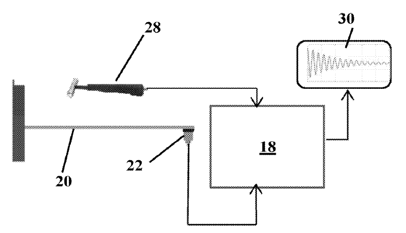
US10837945 — PROCESS FOR FORMING AND QUALITY PROOFING A FRICTION STIR WELDED PLATE — King Abdulaziz University (Saudi Arabia) — A method for determining a quality of a friction stir welded seam is described. The method involves applying an impact to a welded plate and comparing its damping capacity with the damping capacity of a geometrically equivalent defect-free plate. Damping capacities that differ by a small percent difference indicate that the welded plate is also defect-free. This method is particularly advantageous when dealing with small defects, which produce miniscule changes in natural frequency which may not be measureable. As part of the experimental procedure, aluminum alloy AA1060 plates were used as the base metal.
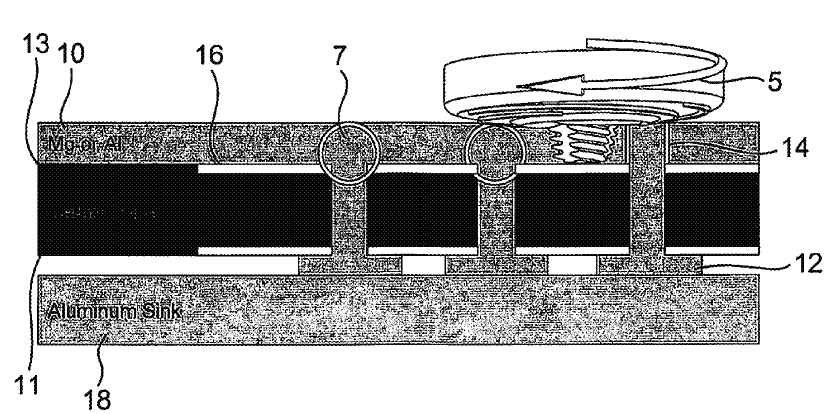
US10835989 — METHOD FOR FRICTION STIR WELDING AND FRICTION STIR WELDED WORKPIECE — Universitaet Stuttgart (Germany) — In a method of friction stir welding two pieces of material of greatly differing melting temperatures, provision is made that the first piece of material is overlapped by the second piece of material. The rotating pin of the friction stir welding tool provides for a butt joint welding and an overlap welding at the same time in that the pin is moved along the face side and contacts it either not at all or at most to a minimum extent. The same also applies to the planar side of the first piece of material, which is overlapped by the less stable piece of material. Preferred material pairings for the first and second pieces of material are steel (first piece of material) and aluminum or copper (second piece of material) or copper for the first piece of material and aluminum for the at least one second piece of material. The materials that can be used for the first and/or the second piece of material may also be wrought or cast materials.
US10807146 — METHOD AND APPARATUS FOR PRODUCING A HYBRID CONNECTION — Ford Global Technologies, LLC (USA) — The disclosure provides a method for connecting a sandwich element to a metal element so that a component, in particular a motor vehicle component, can be produced which, despite lower production costs, fulfills the necessary rigidity and/or crash requirements whilst giving the greatest possible consideration to weight. A method for producing a connection between a sandwich element and a metal element is disclosed herein. In this method, the sandwich element has an interlayer arranged between two cover elements. The method includes providing the sandwich element and the metal element; placing the sandwich element and the metal element in face-to-face contact at least partially overlapping; adding a fastener from the sandwich-element side while a base of the fastener extends within the sandwich element; and friction welding, from the metal-element side, to form a hybrid connection having a mechanical connection between the fastener and the sandwich element and a welding connection between the fastener and the metal element.
US10799979 — SYSTEMS AND METHODS FOR DETERMINING EFFICIENCY OF FRICTION WELDING PROCESSES — Ohio State Innovation Foundation and Government of the United States as Represented by the Secretary of the Air Force (USA) — Systems and methods for calculating efficiency of a rotary friction welding process are described herein. An example method can include measuring kinetic energy transferred from a welding machine to an interface of a welded joint and calculating an efficiency of a rotary friction welding process based on the measured kinetic energy. For example, a workpiece torque experienced by a sample can be measured, and an energy associated with the workpiece torque can be calculated. The efficiency of the rotary friction welding process can then be calculated using the energy associated with the workpiece torque.
US10766626 — SINGLE-PIECE EXTENDED LAMINAR FLOW INLET LIPSKIN — The Boeing Company (USA) — Jet engines and turbofan jet engines are surrounded by an annular, barrel-shaped nacelle. At least some known nacelles include a lipskin at the leading edge, or inlet, of the nacelle. Methods are disclosed for forming metal workpieces made from a heat-treatable metal that has been shaped and tempered according to specified protocols that facilitate formation of large contoured unitary metal structures having welds that are retained in the finished structure, and finished metal structures made according to such methods. In one aspect, the shaped metal workpiece comprises a friction stir weld.

US10744592 — FRICTION STIR WELDING TOOL MEMBER MADE OF SILICON NITRIDE SINTERED BODY AND FRICTION STIR WELDING APPARATUS USING SAME — Kabushiki Kaisha Toshiba and Toshiba Materials Co., Ltd. (Japan) — The present invention provides a welding tool member for friction stir welding comprising a silicon nitride sintered body, wherein the silicon nitride sintered body includes an additive component other than silicon nitride in a content of 15% by mass or less, and the additive component includes three or more elements selected from Y, Al, Mg, Si, Ti, Hf, Mo and C. It is preferable that the content of the additive component is 3% by mass or more and 12.5% by mass or less. It is also preferable that the additive component includes four or more elements selected from Y, Al, Mg, Si, Ti, Hf, Mo and C. Due to above structure, there can be provided a welding tool member for friction stir welding having a high durability.
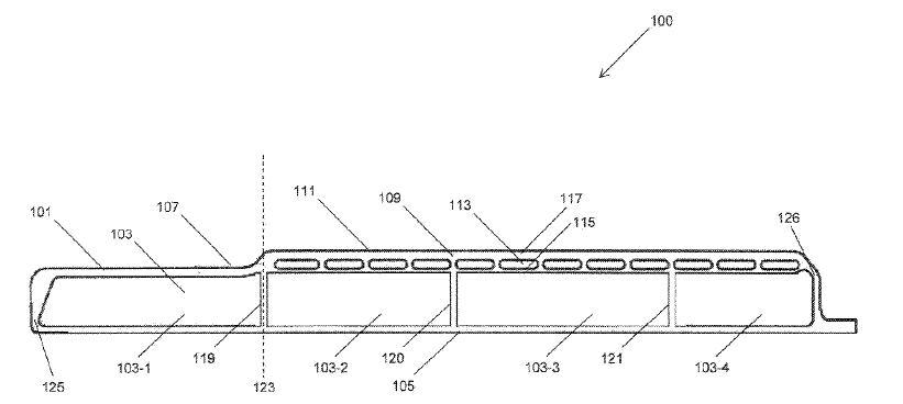
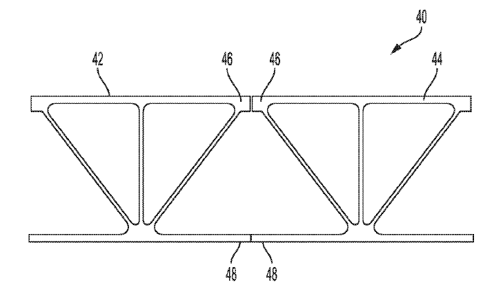
US10730661 — CARGO PALLET WITH EXTRUDED SLOT — HFW Solutions, Inc. (USA) — A panel structure comprised of a plurality of extruded aluminum panel members. The aluminum panel members are joined together into a single structure by a friction stir welding process and at least one of the extruded aluminum panel members includes an extruded slot running along an entire length of the at least one of the extruded aluminum panel members. The extruded slots are used to attach hooks or other suitable retaining devices for securing objects to the panel structure or to directly attach structural elements or modules to the panel structure. n the present application, at least one of the aluminum panel members is extruded with a T-slot that is used for fastening cargo in location with flexibility. T-slots are used in many applications from computer numerical control (CNC) beds to seat rail tracks for airplanes. There are many designs available, and many accessories to facilitate restraint. The advantage of T-slots is their ability to accommodate restraint in a variety of positions along their length. By utilizing extruded aluminum to form the T-slot, they can be produced for a relatively low cost compared to machining a similar T-slot from bar or plate stock.
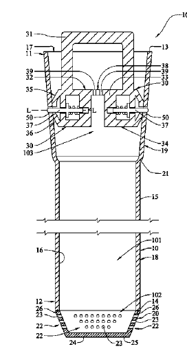
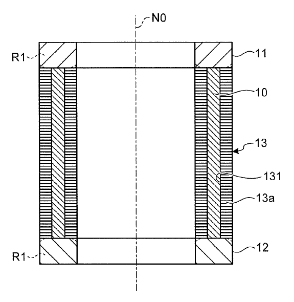
US10692617 — CONTAINER AND SYSTEM FOR HANDLING DAMAGED NUCLEAR FUEL, AND METHOD OF MAKING THE SAME — Holtec International (USA) — A container and system for handling damaged nuclear fuel, and a method of making the same. In one embodiment, the invention is a damaged fuel container having a specially designed top cap that can be detachably coupled to the elongated tubular wall by simply translating the top cap into proper position within the elongated tubular wall, wherein biased locking elements automatically lock the top cap to the elongated tubular wall. In another embodiment, the vent screens of the damaged fuel container are integrally formed rather than being separate components. In still other embodiments, the lower vent screens are arranged on an upstanding portion of the damaged fuel container. In an even further embodiment, the elongated tubular wall is formed by extrusion of an aluminum-boron carbide matrix composite material and the bottom cap is friction stir welded to the bottom end 12 to the elongated tubular wall 10.
US10688592 — FRICTION STIR WELDING OF ALUMINUM ALLOYS — United Launch Alliance, L.L.C. (USA) — The present invention is directed to friction stir welding, and to apparatuses, methods, and systems using friction stir welding to join one or more components comprising an aluminum 2xxx alloy with one or more components comprising an aluminum 7xxx alloy. The aluminum 2xxx alloy may be in the form of a filler insert, for example a sheet or strip, between two larger aluminum 7xxx alloy components, or the aluminum 2xxx alloy may be in the form of a larger component welded directly to an aluminum 7xxx alloy component of comparable size. Weldments according to the present invention have improved resistance to stress corrosion cracking without the need for post-weld artificial aging and are useful in many applications, for example in construction of spacecraft parts.
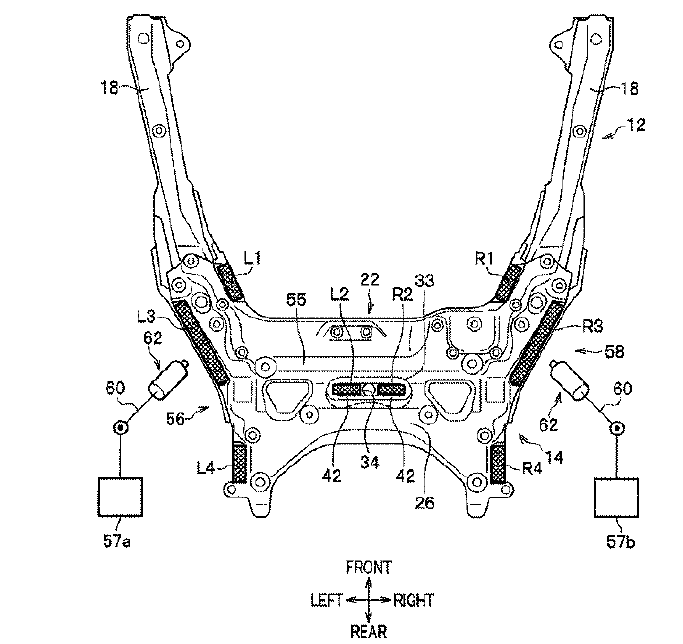
US10640153 — DIFFERENT MATERIALS JOINT STRUCTURE — Honda Motor Co., Ltd. (Japan) — A subframe structure includes a frame front part and a frame rear part in a vehicle front-rear direction. The frame front part and the frame rear part are joined together. The frame front part has a higher strength than the frame rear part. The subframe has different strengths from part to part. The frame front part is made of a galvannealed steel plate (GA steel plate) subjected to an electrodeposition coating. The frame rear part is made of a hot-dip galvanized steel plate (GI steel plate) subjected to an electrodeposition coating. A rear cross member of an aluminum die-casting and a rear cross panel of a hot-dip galvanized steel plate (GI steel plate) are integrally joined together by a friction stir welding. In the present invention, it is possible to obtain a different materials joint structure which achieves all of a reduced weight and a high strength characteristic, a faster friction stir welding rate, and the improvement of corrosion resistance reliability, as compared with the conventional techniques.
US10549379 — FRICTION STIR WELDING METHOD AND JOINED BODY — Kabushiki Kaisha Toshiba (Japan) — A friction stir welding method includes joining a first metal member, a second metal member, and a third metal member by pressing a tool onto a joining member while rotating the tool. The tool has a protrusion at a tip of the tool. The joining member includes the first metal member, the second metal member, and the third metal member. A major element of the second metal member is the same as a major element included in the first metal member. The third metal member is sandwiched between at least a portion of the first metal member and at least a portion of the second metal member. A major element of the third metal member is the same as the major element included in the first metal member and the second metal member. A crystal grain size of the third metal member is 20 μm or less. Long fatigue life of the joining portion periphery is desirable for the members after the joining. The major element of the second metal member, and the major element of the third metal member are aluminum, magnesium, titanium, copper, steel, zinc, lead, or an alloy of these elements.

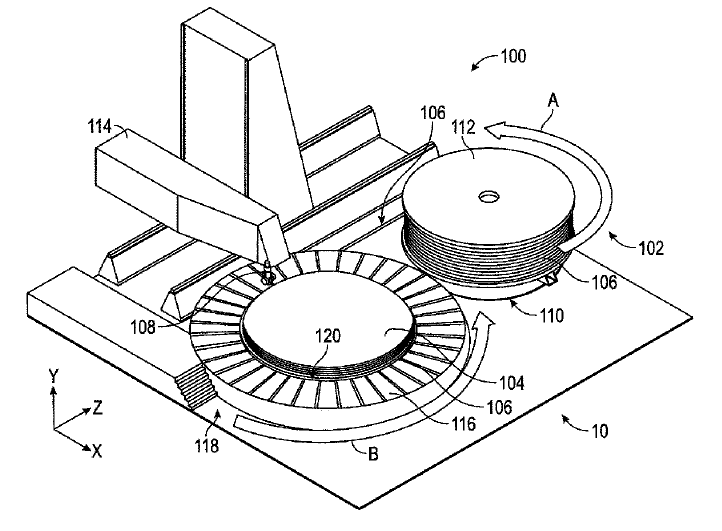
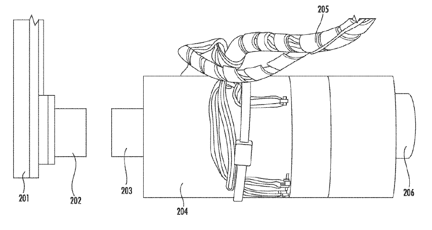
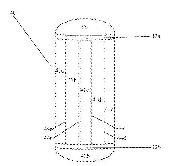
US10505432 — ROTOR AND METHOD FOR MANUFACTURING ROTOR — NHK Spring Co., Ltd. (Japan) — A rotor includes: conductors having a bar shape; a first end ring joined to one ends of the conductors by friction stir welding, at least a surface opposite to a surface from which the conductors extend being stirred by the friction stir welding; a second end ring joined to other ends of the conductors by friction stir welding, at least a surface opposite to a surface from which the conductors extend being stirred by the friction stir welding; and an iron core disposed between the first and the second end rings, having a cylindrical shape, and including a plurality of insertion holes through which the respective conductors are insertable in a central axis direction of the iron core.
US10465266 — HEAT-RESISTANT TUNGSTEN ALLOY, FRICTION STIR WELDING TOOL, AND PRODUCTION METHOD — A.L.M.T. Corp. (Japan) — The present heat-resistant tungsten alloy has a first phase containing W as a major component, a second phase having a carbonitride of at least one element of Ti, Zr and Hf and containing the carbonitride as a major component when W is removed, and a third phase having a carbide of at least one element of group 5A elements in the periodic table and containing the carbide as a major component when W is removed, the heat-resistant tungsten alloy having a Vickers hardness of 550 HV or more at a room temperature, a displacement of 1 mm or more when leading to fracture, as determined in a three point bending test at 1200°C, and a 0.2% proof stress of 900 MPa or more, as determined in the three point bending test at 1200°C.
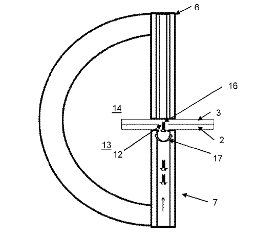
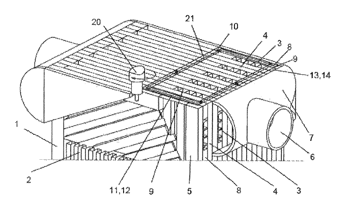
US10378832 — METHOD FOR PRODUCING A PLATE HEAT EXCHANGER USING TWO WELDS, AND A CORRESPONDING PLATE HEAT EXCHANGER — Linde Aktiengesellschaft (Germany) — A method for producing a plate heat exchanger and the plate heat exchanger, particularly a soldered aluminum plate heat exchanger. In the method, a heat exchanger block is provided having a plurality of partition plates and edge strips arranged between the partition plates. A connection device is provided to be mounted on the heat exchanger block. A planar region for securing the connection device to the heat exchanger block is provided with at least one welded weld bead by means of a first weld. The connection device is welded onto the weld bead by means of a second weld. The welding method used for the first weld is a friction stir welding method.
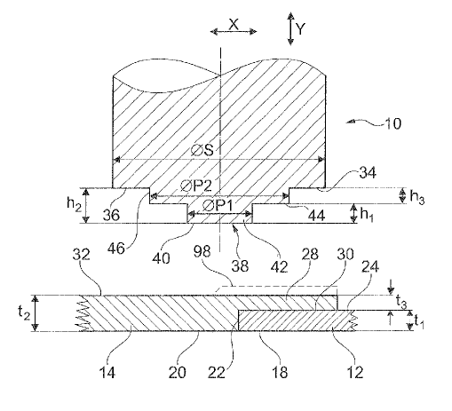
US10369748 — FRICTION STIRRING INTERLOCKING OF DISSIMILAR MATERIALS — Battelle Memorial Institute (USA) — A method for solid state joining of dissimilar materials using a friction stir welding device wherein a pin is inserted through an aperture defined in a first material, which can be steel or aluminum, and a second material, which can be aluminum or steel, to hold the materials together and then held in place by friction stir welding a portion of the pin to a material adjacent said pin, or by friction stir welding a cap or plug that holds the pin in place to the adjacent material. The result is a connection or join wherein the central portion of the pin is not friction stir welded but the portions holding the pin in place (the ends or caps) generally are.
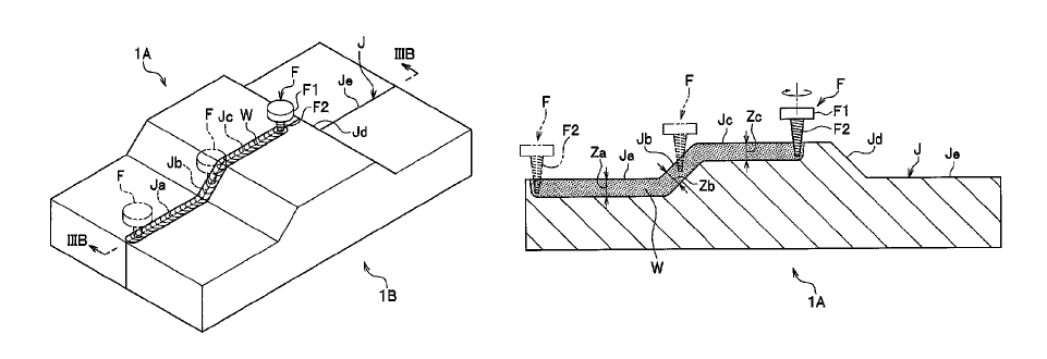
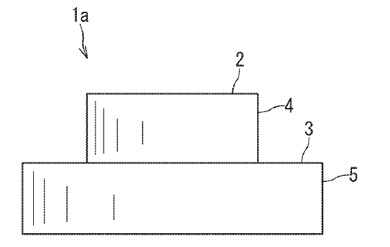
US10335894 — JOINING METHOD — Nippon Light Metal Company, Ltd. (Japan) — A joining method includes a butting process configured to butt a first metal member and a second metal member each having a front surface with various heights to form therebetween a butt portion with various heights; and a welding process configured to apply a friction stirring to the butt portion by a stirring pin of a rotation tool while only the stirring pin of the rotation tool contacts with the first metal member and the second metal member of the butt portion. The welding process may be configured to insert the stirring pin of the rotation tool into the butt portion from front surfaces of the first metal member and the second metal member and apply the friction stirring to the butt portion while an insertion depth of only the stirring pin is kept approximately constant.