Based in Riverside, CA, Sierra Aluminum is a 100% employee-owned extrusion company that manufactures standard and custom extrusions on seven UBE presses—two 7 inch presses, four 8 inch presses, and one 9 inch press. Downstream of the presses, Sierra has two paint lines, a modern anodizing line, and fabrication capability to supply a wide customer base out of their two locations in Riverside and Fontana. The casting line located in the Riverside plant was installed in 1990 and expansion of a second melting and homogenizing furnace was completed in 1999 to meet the growing demands from the presses. Over a number of years, the products produced from the casting pit typically exhibited straightness issues. The extent of bend in the billet was originally acceptable, but as Sierra continued to modernize and update their extrusion capabilities and set tighter quality limits, the “banana” bend in the billets created production issues downstream and the management realized they needed a solution.
Sierra contracted with Dynamic Concept through their partner company AluMore to perform upgrades of its casting pit in order to improve the product quality at its casting and extrusion facility. A two-step approach was taken to resolve the issue. First, an order was placed with Dynamic Concept to conduct an audit of the pit and identify the cause of the billet deviation. Once the audit was complete, a second order was placed with the supplier company to implement the modifications required to resolve the issue.
Casting Pit Audit
The first phase of the project was to execute a complete casting pit audit to identify the root issues of the problem. Many factors can contribute to billet straightness issues, both mechanical and process related. Mechanically induced bending can result from tooling (platen, head base, table) misalignment, cylinder issues, guide rail alignment, and a range of set-up anomalies. Similarly, non-uniform solidification rates caused by cooling water variations or metal temperature distribution can result in solidification induced bending of the billets.
The audit at Sierra was conducted over a three-day period with the engineering team evaluating all the potential contributing factors through process review, analysis, and measurement of the tooling systems, review of the characteristics and the magnitude of the billet deviation, and a full mapping and measurement of the casting pit.
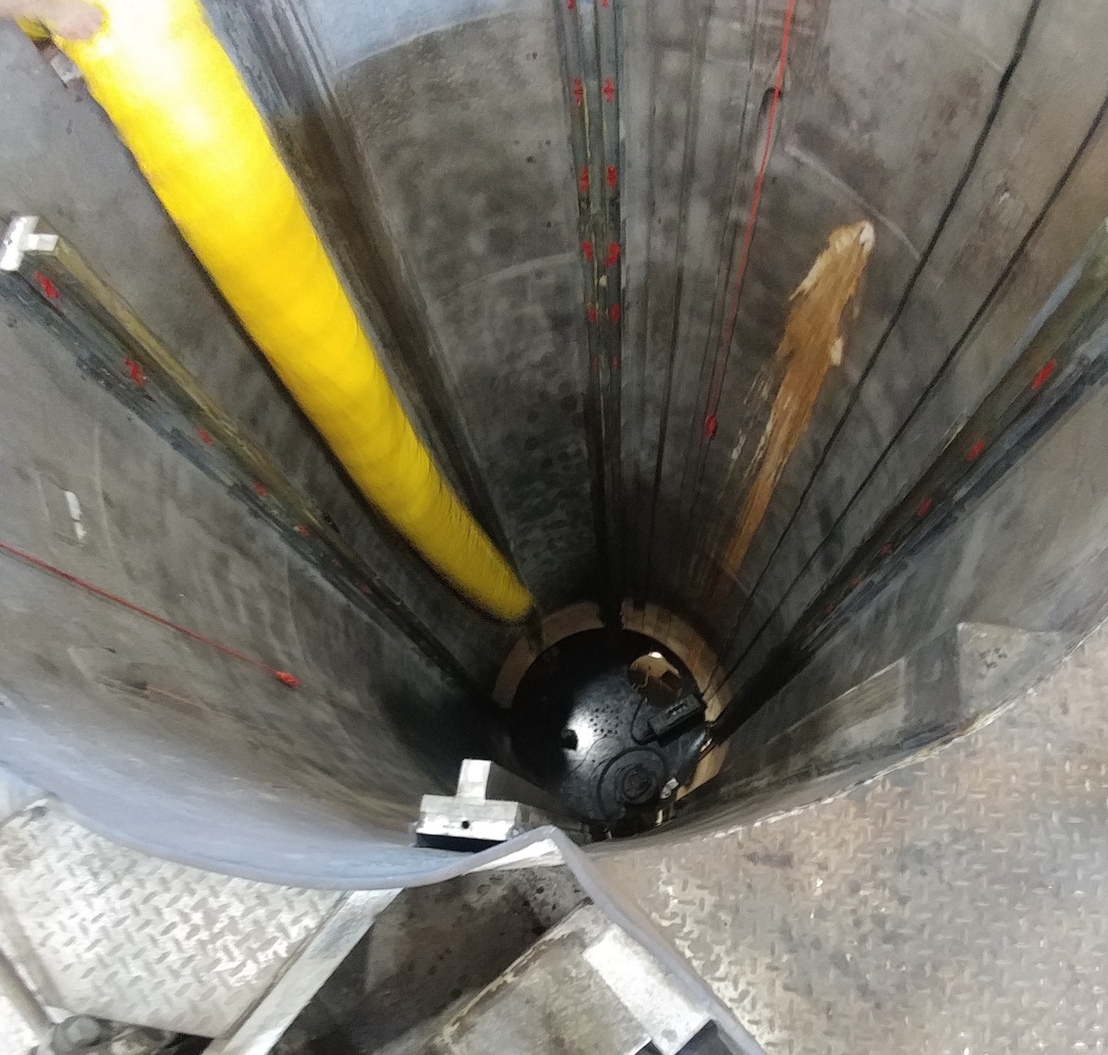
3D Laser Scanning of the Casting Pit
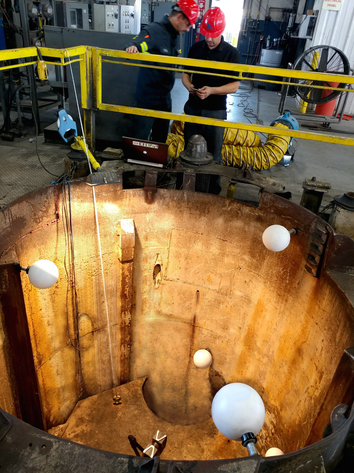
A common symptom of casting pits with externally guided cylinders is the linearity of the guide rails, where the pit wall mounted rails can lose their linearity through damage, pit wall anomalies, exposure to bleed-outs, and simple wear and tear over the years in service. In consideration of this, a significant part of the audit was to conduct a three-dimensional metrology study using a FARO 3D laser scanning device. The scanner measures the angle, distance from the horizon, and orientation for millions of separate points. The accumulation of measurement points for a given surface provides very high accuracy and can then be translated into a three-dimensional model.
Placing the laser scanner on the platen and providing an array of reference nodes in and around the pit (Figure 1), the platen was lowered completely and then raised in 12 inch increments with a scan made at each point. This procedure continued until the platen was at the fully raised position.
Following a preliminary field review to ensure all data had been collected and a debrief with the client, the engineering team left the site to perform a data analysis of the scanner results and to correlate all other information obtained during the site visit to determine the root cause of the bending issue.
Data Evaluation and Results
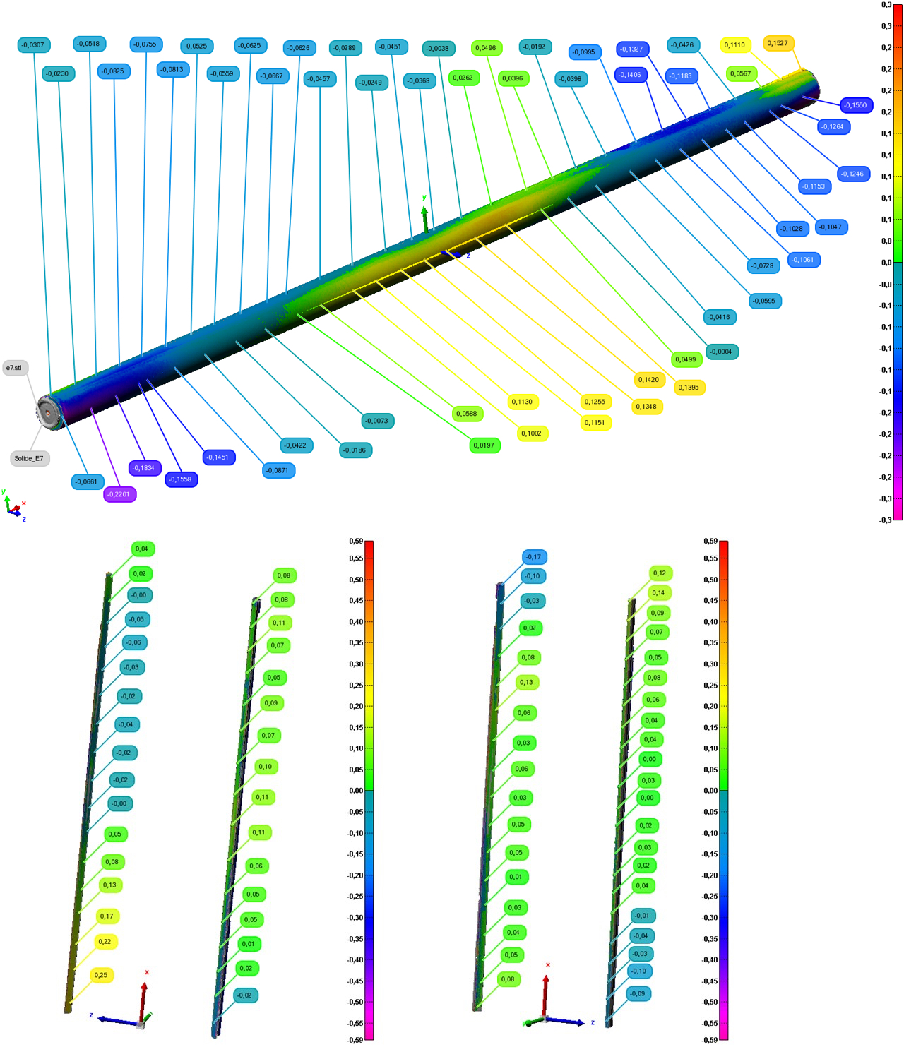
Despite the high accuracy of the FARO laser scanning device, the system is extremely sensitive to external influences including movement, temperature changes, and vibration. A small amount of cylinder drift that had been identified when the cylinder was at maximum stroke was found to be sufficient to invalidate the scan results for the top section of the casting pit. Considerations were also made that all of the scan data were collected in an “unloaded” cylinder condition and the effects of a typical cast load may affect the nature of the platen and guide rail interface.
With these observations considered, the correlation of the data from the laser scanning (Figure 2), billet measurements, and other filed data led to the conclusion that two primary and interrelated situations were the cause of the bent billets. First, there was a misalignment of approximately 0.25 inches in the guide rails. Secondly, platen movement in both lateral and angular axes were observed, so combining these two effects would be sufficient to produce the billet bow of up to 0.42 inches, as observed in field measurements.
Based on the audit evaluation, a solution was proposed to replace the existing guide rails and replace the existing platen with one that incorporated a spherical bearing attachment between the platen and the casting cylinder. By installing new, adjustable rails, the guide rail alignment tolerance could be guaranteed and by removing the fixed connection between the cylinder and the platen, any influence of cylinder misalignment would be isolated from the platen movement. Following approval from the management of Sierra Aluminum, the engineering phase of the project was initiated.
Casting Pit Upgrades
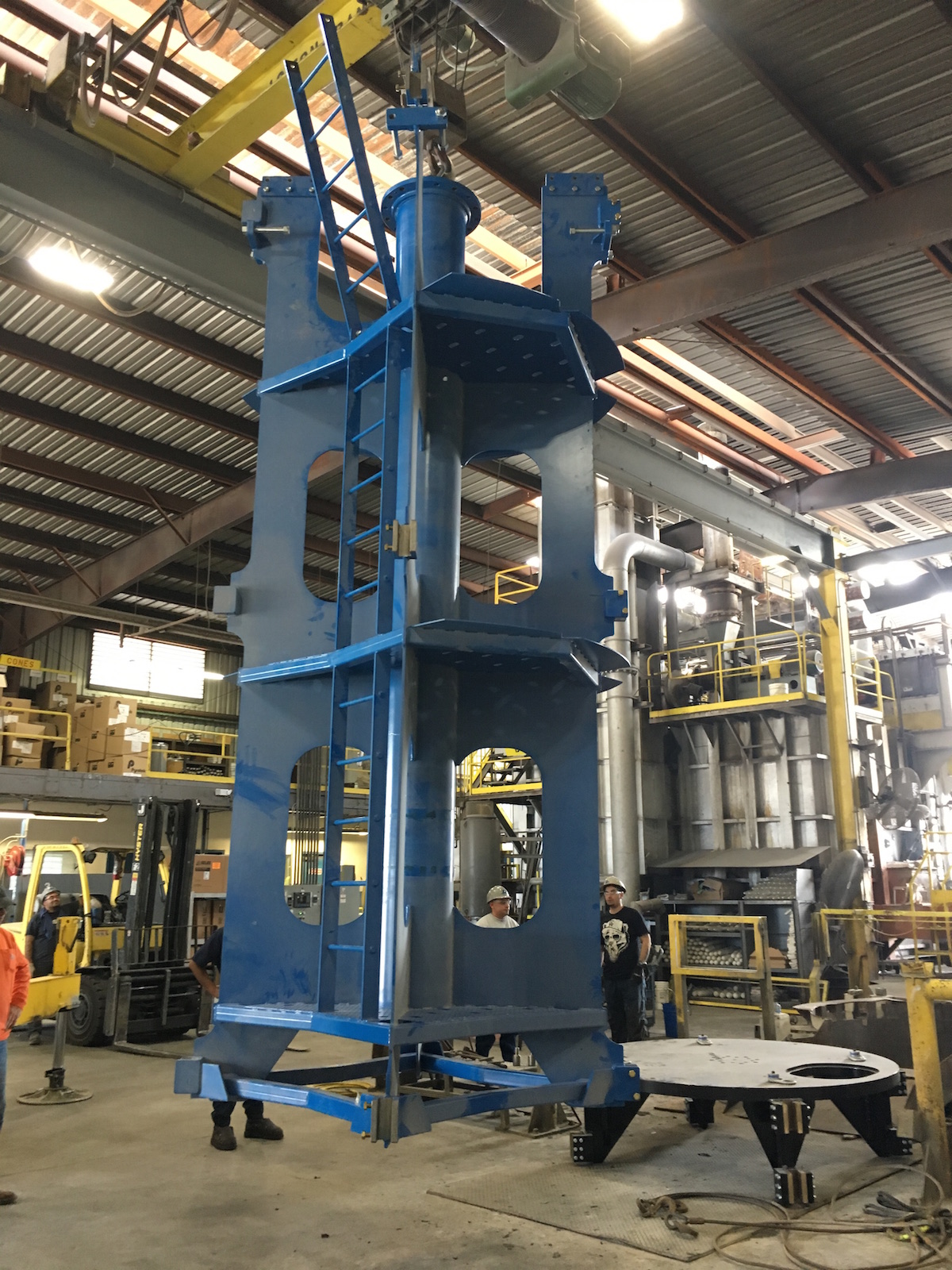
The casting pit at Sierra Aluminum is cylindrical in shape with a steel caisson providing the pit wall. Following 28 years of operation, the wall of the casting pit is no longer uniform, so a new guide rail system design needed to accommodate for these imperfections. A single use, full height jig fixture was designed by the Dynamic Concept engineers that could be installed in the casting pit and provide support and accurate location positioning for the guide rails (Figure 3). It also provided a series of working platforms for the installers to use throughout the entire casting pit without the need for temporary scaffolding (Figure 4).
Safety Considerations
Before any work was started on the installation, safety protocols were reviewed in detail by Sierra Aluminum’s safety director. This included confined space protocols, the need for continual air circulation, harness requirements, external monitoring of air sensors, and communication protocols. Following this and prior to installation of the new guide rail system, the casting pit was sandblasted to remove the existing pit coating and any rust and debris on the wall surface. At completion of the project, the clean, rust free pit wall was completely recoated with Wisechem® prior to returning to production.
Because of the cylindrical pit design, the Wagstaff AirSlip® tables use a non-standard mold configuration to optimize the mold density for the 7 inch, 8 inch, and 9 inch tables. Due to this configuration, the available space for the pit and cylinder revisions presented a significant design challenge. As the original tooling systems were being retained, attention was paid to the design of the new platen and guide rails to ensure all clearances remained within the recommendations of the Aluminum Association’s Guidelines for Handling Molten Aluminum.
Installation
Considering the pit wall was a steel caisson, the guide rails were designed to be welded to the pit wall. The accuracy of this welding process was extremely critical and was carried out by two of the Sierra Aluminum maintenance crew with continual tolerance checks by the Dynamic Concept lead engineer. The entire team of welders, inspector, and safety observers worked diligently for three full days in safe but cramped and less than comfortable conditions to complete the work. The end result was all four rails being installed within a few thousandths of an inch of straightness and well within the tolerance and adjustability limits required by the system design.
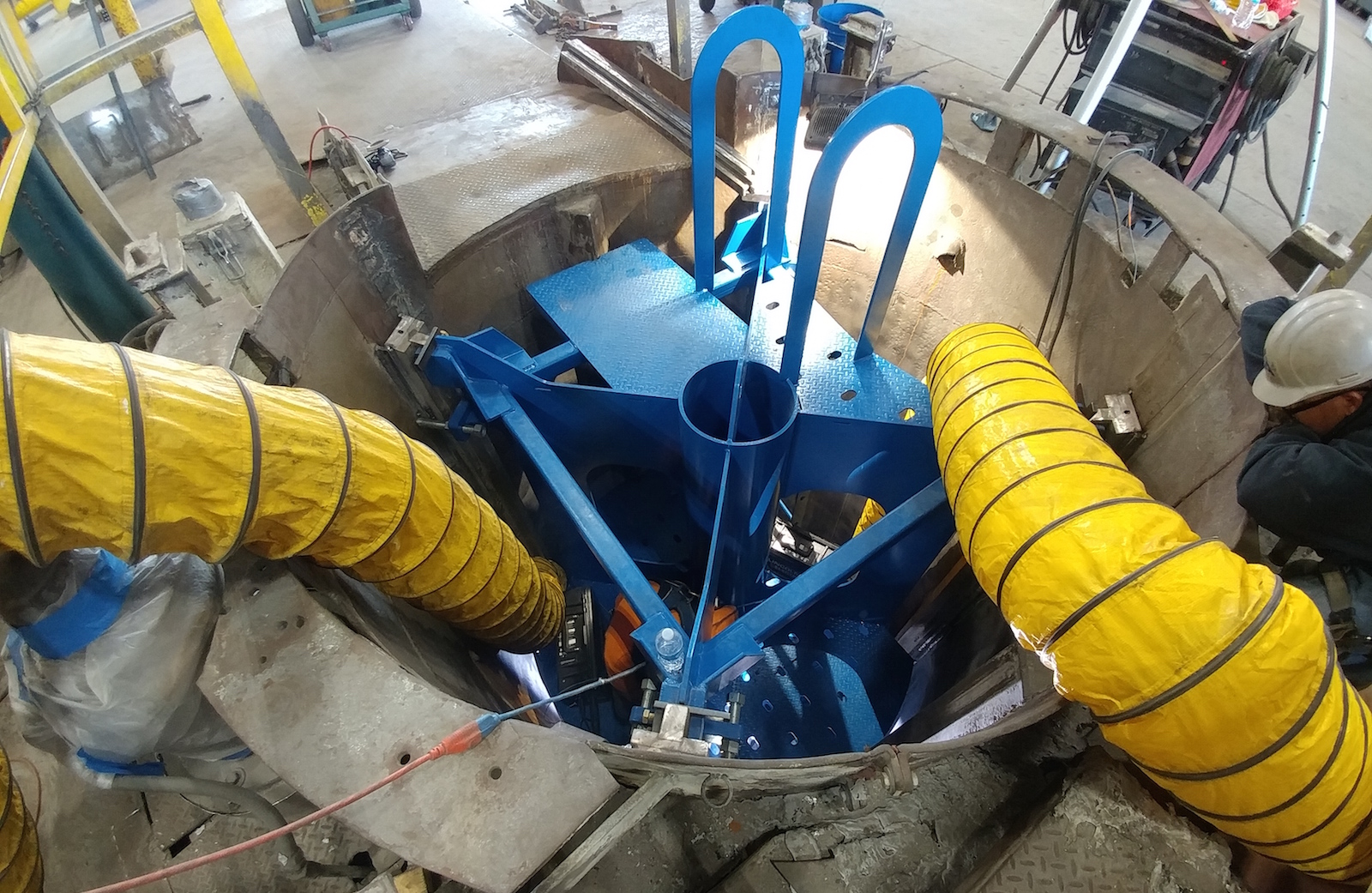
Upon completion of the rail installation, the jig was removed from the pit, the new platen was installed (Figure 5), and the mating guide rail shoes adjusted. The cylinder was then put through numerous motion trials to ensure there were no hang-ups, tight spots, or interferences that could affect product quality or safe operation of the casting pit. After ensuring the three different head bases were all located correctly onto the platen, the pit was fully cleaned and painted with Wisechem coating.
Start-Up
As soon as the coating had fully cured, the casting line was prepared for resumption of casting three days ahead of the original schedule. The first cast was made using the 7 inch casting table, which traditionally experienced the most severe bending. After a successful cast, the billets were removed from the pit and the straightness measured both visually and by means of a taut wire. The requirement from Sierra Aluminum for billet straightness was for the product to be of similar quality to primary smelter billet. This target was achieved to the satisfaction of all parties and, most importantly, the billet performance is now compatible with the downstream process and quality requirements of Sierra Aluminum on all billet diameters.
Conclusion
The ability to conduct a full process and equipment analysis to discover the root causes of the billet bending issues at Sierra Aluminum was critical in order to correctly ascertain the full scope of the factors affecting the product quality. The novel approach of building a full-length jig that would accurately position the new guide rails and provide access to the installation crews for safe and accurate installation of the rail systems expedited the installation process and ensured an installation accuracy that otherwise would not have been matched. Exceptional communication and support by all parties was the other important factor that ensured a successful and ahead-of-schedule project completion.
Editor’s Note: This article first appeared in the June 2018 issue of Light Metal Age. To receive the current issue, please subscribe.