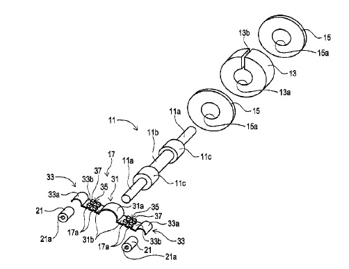
US10210966 — INSULATED WIRE AND COIL — Furukawa Electric Co., Ltd. And Furukawa Magnet Wire Co., Ltd. (Japan) — An insulated wire, containing: a rectangular conductor; and a thermoplastic resin layer on the rectangular conductor, wherein an adhesion strength between the thermoplastic resin layer and the rectangular conductor for a pair of sides of the rectangular conductor opposed to and an adhesion strength between the thermoplastic resin layer and the rectangular conductor for the other pair of sides of the rectangular conductor opposed to are different from each other. In a case where the rectangular conductor is composed of aluminum alloys, examples thereof include 1000-series aluminum alloys which have a low strength but a high aluminum ratio, and Al–Mg–Si-series alloys, for example, 6101 alloy of 6000-series aluminum alloys. As for the aluminum or aluminum alloys, its electric conductivity is about 2/3 of the copper or copper alloys. However, its gravity is about 1/3 of the copper or copper alloys. Accordingly, reduction in weight of the coil can be achieved, which allows a contribution to lightening of vehicle and improvement in fuel economy.
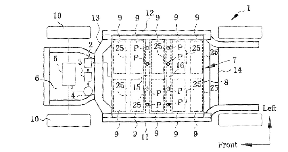
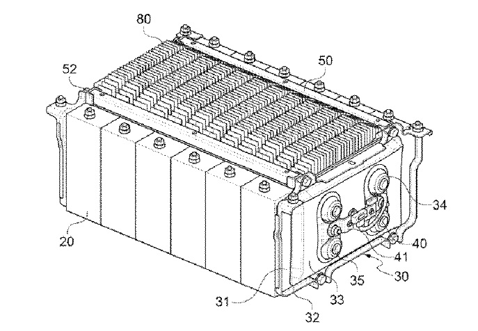
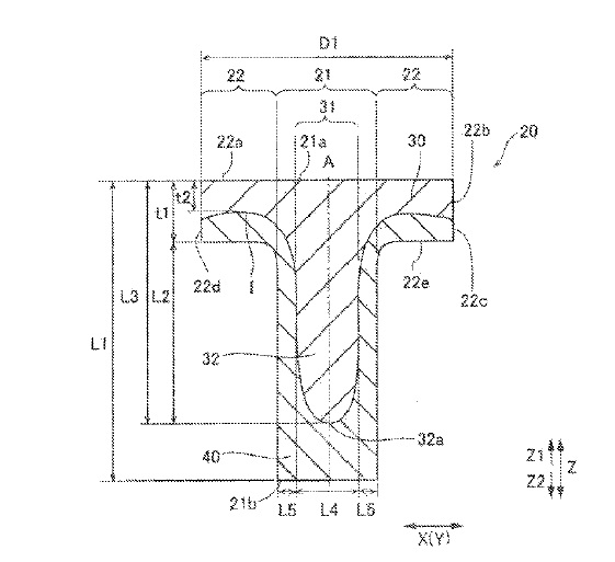
US10207573 — BATTERY MOUNTING STRUCTURE FOR VEHICLE — Toyota Jidosha Kabushiki Kaisha (Japan) — A battery mounting structure for maintaining a sufficient passenger compartment in vehicles is provided. The battery mounting structure comprises a pair of longitudinal side sills (11, 12), and a battery pack (7) disposed between the side sills (11, 12). A plurality of battery modules (9) are juxtaposed in a casing (8) of the battery pack (7). A linear depression (39) protrudes downwardly from a reinforcement member (15) situated underneath a floor panel (17) supported by the side sills (11, 12), and the battery pack (7) has a linear depression (38) hold the linear depression (39) therein. In order to lighten the vehicle weight while ensuring rigidity, each of the right side sill 11 and the left side sill 12 may be formed using light aluminum alloy by an extrusion method in such a manner as to maintain a hollow space 33 therein.
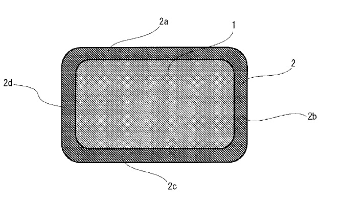
US10205429 — OUTPUT-NOISE REDUCTION DEVICE — Kitagawa Industries Co., Ltd. (Japan) — An object is to provide an output-noise reduction device that can prevent noise from an electronic device accommodated in an aluminum casing, e.g., an aluminum die casting, from being transmitted due to electromagnetic coupling. An output voltage is extracted to the outside through a conducting bar. A magnetic body core includes a through hole through which the conducting bar is inserted. A chip capacitor is mounted on a mounting board and connects between the output terminal VO and ground potential. A section from the output terminal VO to at least part of the chip capacitor mounted on the mounting board is isolated from the electromagnetic coupling from the electronic device. Thus, noise is prevented from being transmitted to the output terminal VO.
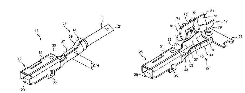
US10205252 — CONNECTING STRUCTURE OF CRIMP TERMINAL AND ELECTRIC WIRE — Yazaki Corporation (Japan) — A structure for connecting a crimp terminal and an aluminum electric wire includes: a crimp terminal that includes a conductor crimping portion and a coating crimping portion serially and includes an electric wire connector that is to be crimped to the electric wire; and a water stop sheet having an opening for bringing a conductor into contact with the conductor crimping portion, and laid between the electric wire connector and the electric wire. When a joint is swaged and crimped, the swaged and crimped joint has a second included angle θ2 between the bottom plate and a second line that is larger than a first included angle θ1 between the bottom plate and a first line in a cross section that is perpendicular to a bottom plate of the electric wire connector and that includes an electric wire axial line.
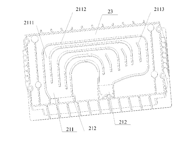
US10205203 — COOLING SYSTEM FOR BATTERY PACK — Contemporary Amperex Technology Co., Limited (China) — The present invention provides a cooling system for a battery pack, comprising: a housing, an air passage, a fan. and at least two air holes; the housing comprises an upper cover and an aluminum alloy box, the upper cover is connected with an aluminum alloy box; the air passage is arranged on the box and comprises an airflow cavity, an air channel and an air hole; the airflow cavity is arranged at a bottom of the box which contains an aluminum alloy plate; the air channel is arranged on a side wall of the box, and the bottom of the air channel is communicated with the airflow cavity; all the air holes are arranged on the housing and communicated with the air passage, wherein at least one air hole is arranged on the upper cover and corresponds to a top end of the air channel; and the fan is arranged inside the air passage.
US10205201 — COOLING SYSTEM FOR BATTERY — Samsung SDI Co., Ltd. (Korea) — A cooling system for a battery reduces a cooling package space using a duplex pipe and can reinforce mechanical strength of the duplex pipe by forming reinforcement ribs in the duplex pipe. The cooling system includes a duplex pipe and an internal unitary pipe connected to the duplex pipe and arranged at a side of a battery cell, the internal unitary pipe including an internal inlet to flow a cooling fluid into the internal unitary pipe and an internal outlet to flow the cooling fluid from the internal unitary pipe. The pipes and associated cooling plate can be made of an aluminum alloy with good heat transfer efficiency.
US102205182 — FUEL CELL SYSTEM — Honda Motor Co., Ltd. (Japan) — Oxidant gas flows to the fuel cell stack through an oxidant gas supply channel. Oxidant off-gas is discharged from the fuel cell stack through an oxidant off-gas exhaust channel. A refrigerant is discharged from the fuel cell stack through a refrigerant exhaust channel. An outlet sealing valve is provided in the oxidant off-gas exhaust channel. The outlet sealing valve includes a main body, a valve seat, a valve body, and a refrigerant passage. The main body has a passage through which the oxidant off-gas flows. The valve seat is provided in the passage. The valve body is provided in the passage to be seated on the valve seat to close the passage. The refrigerant passage is branched off from the refrigerant exhaust channel. The refrigerant flows in a vicinity of at least one of the valve seat and the valve body through the refrigerant passage. The anode system 2 is intended to supply or exhaust hydrogen to or from an anode of the fuel cell stack The anode system cover 25 is a housing which is made of an aluminum alloy and has relatively high rigidity and protects pieces of equipment of the anode system 2 from a load at the time of a vehicle collision. Since the anode system cover 25 surrounds the anode system 2, the anode system cover 25 functions as a sound-proof wall which makes it harder for a driver to hear working noise from the first injector 21 or the like, or functions as a container which keeps hydrogen leaking out from the anode system 2 from diffusing into a motor room 110.
US10205170 — COPPER FOIL FOR CURRENT COLLECTOR OF LITHIUM SECONDARY BATTERY — Chang Chun Petrochemical Co., Ltd. (Taiwan) — The negative electrode current collector of a lithium secondary battery is generally made using copper foil. The negative electrode is formed by coating the surface of the copper foil (current collector) with carbon powder, or other negative electrode active materials processed to a paste, drying this paste, then press flattening the negative electrode active materials by rolling or other pressure application. This composite of copper foil and compressed negative electrode active material is then, together with a separator, and an aluminum foil coated with a positive electrode active material, rolled up to form a cylindrical lithium secondary battery. Electrodeposited copper foils having adequate puncture strength to withstand both pressure application during consolidation with negative electrode active materials during manufacture, as well as expansion/contraction during repeated charge/discharging cycles when used in a rechargeable secondary battery are described. These copper foils find specific utility as current collectors in rechargeable secondary batteries, particularly in lithium secondary battery with high capacity. Methods of making the copper foils, methods of producing negative electrode for use in lithium secondary battery and lithium secondary battery of high capacity are also described.
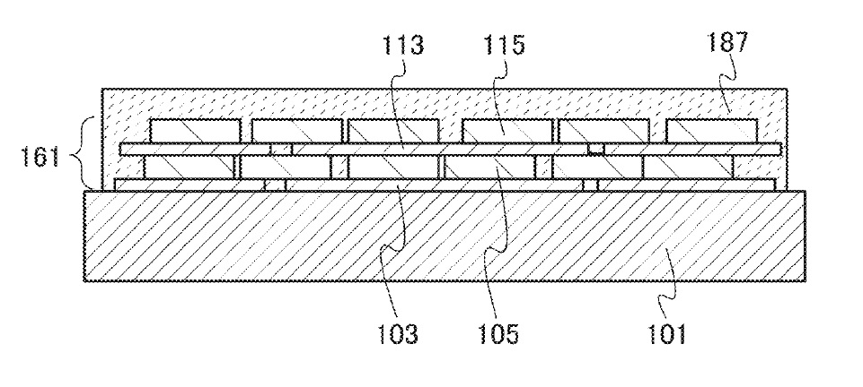
US10205160 — GRAPHENE COMPOSITE OXIDE LAYERED ELECTRODE FOR LITHIUM-ION SECONDARY BATTERIES — Semiconductor Energy Laboratory Co., Ltd. (Japan) — To provide a lithium-ion secondary battery having higher discharge capacity and higher energy density and a manufacturing method thereof. The lithium-ion secondary battery includes a positive electrode, a negative electrode, and an electrolyte provided between the positive electrode and the negative electrode. The positive electrode includes a positive electrode current collector 101 made of aluminum and can have a foil shape, a plate shape, a net shape, or the like as appropriate. In the positive electrode active material layer, graphenes and lithium-containing composite oxides are alternately provided. The lithium-containing composite oxide is a flat single crystal particle in which the length in the b-axis direction is shorter than each of the lengths in the a-axis direction and the c-axis direction. Further, the lithium-containing composite oxide is provided over the positive electrode current collector so that the b-axis of the single crystal particle intersects with a surface of the positive electrode current collector.
US10205154 — RECHARGEABLE BATTERY HAVING SHORT-CIRCUIT PROTRUSION — Samsung SDI Co., Ltd. (Korea) — A rechargeable battery includes: an electrode assembly including a first electrode and a second electrode; a aluminum case accommodating the electrode assembly; a first terminal electrically coupled to the first electrode, and a second terminal electrically coupled to the second electrode; a cap plate combined to the case and having a short-circuit hole formed therein; a membrane fixed to the cap plate and arranged in the short-circuit hole, the membrane being deformable to short-circuit the first electrode and the second electrode; and a short-circuit protrusion electrically coupled to the second electrode and arranged above the membrane to protrude theretoward, the short-circuit protrusion being arranged toward a side from a center of the short-circuit hole.
US10205150 — BATTERY PACK BUS BAR ASSEMBLY WITH SHAPED INTERCONNECT MOUNTING PLATFORMS — Atieva, Inc. (USA) — A battery assembly utilizing a compact and robust bus bar configuration is provided. The batteries within the assembly are divided into groups with each group formed from at least two rows of batteries. The batteries within each battery group are connected in parallel and the groups are connected in series. The batteries are interconnected using a plurality of non-overlapping bus bars, which may be made of aluminum, configured in an alternating pattern with the plurality of battery groups, where each of the bus bars includes multiple interconnect mounting platforms. The interconnect mounting platforms simplify coupling multiple rows of batteries to each bus bar while minimizing bus bar current density variations and insuring that individual interconnect resistance remains relatively low and at about the same level per battery.
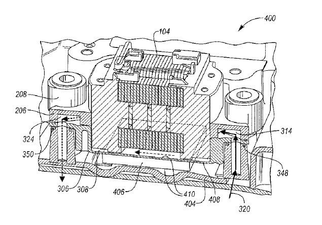
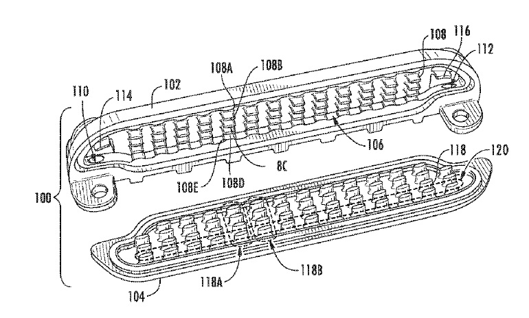
US10204729 — INDUCTOR COOLING SYSTEMS AND METHODS — Ford Global Technologies, LLC (USA) — Inductor cooling systems and methods are disclosed. A vehicle may include a transmission case including a coolant inlet and an inductor assembly having a flange extending around a periphery thereof. The conductor may be formed of an electrically conductive material, such as copper or aluminum, and may be wound into two adjacent helical coils 104. A thermally conductive cover having a sealing surface may form a seal with the flange. A cavity may be defined between the cover and the inductor assembly and configured to receive coolant from the coolant inlet. A thermal interface material (TIM) may be in contact with a surface of the cover and a surface of the transmission case. The TIM may be a solid or a paste-like substance. If the TIM is solid, it may be in a state of compression between a bottom surface of the cover and the surface of the transmission case. The TIM may transfer heat from coolant in the cavity to the transmission case while the coolant is not being circulated.
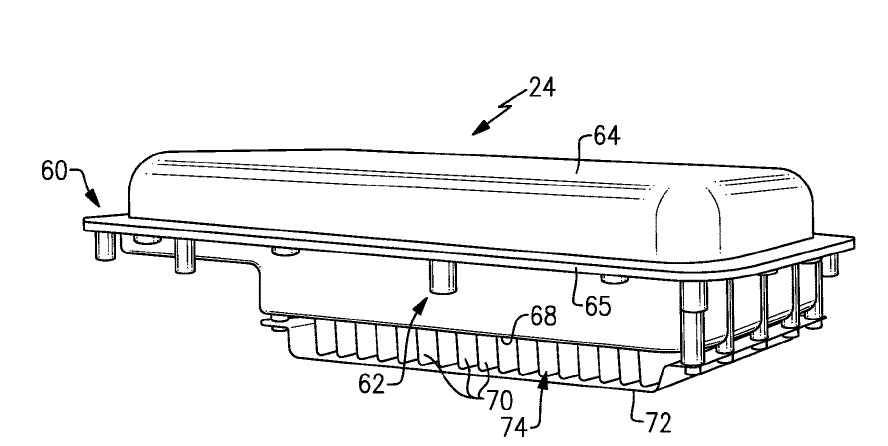
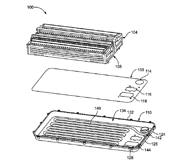
US10199697 — SEALED BATTERY PACK DESIGNS — Ford Global Technologies, LLC (USA) — An exemplary battery pack includes a battery assembly and an enclosure assembly housing the battery assembly. The enclosure assembly is arranged to dissipate heat from at least two sides of the battery assembly. The enclosure assembly 60 could be constructed in a variety of ways using a combination of materials and forming methods. Non-limiting examples of suitable forming methods include stamping, extrusion, casting, and molding. In a non-limiting embodiment, the tray 62 is a cast aluminum tray and the cover 64 is a stamped steel cover. However, other combinations of materials and forming methods are also contemplated within the scope of this disclosure.
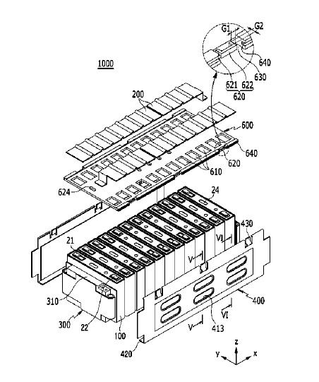
US10199696 — MODULE HOUSING OF UNIT MODULE HAVING HEAT DISSIPATION STRUCTURE AND BATTERY MODULE INCLUDING THE SAME — LG Chem, Ltd. (Korea) — Disclosed herein is a module housing of a unit module including battery cells, the module housing including a first cover member and a second cover member coupled to each other for covering entire outer surfaces of the battery cells, mounting grooves formed at an inside end of at least one of the first and second cover members such that the battery cells are mounted in the respective mounting grooves, and an injection port formed at the module housing such that a thermoplastic resin is injected to interfaces between the mounting grooves and the battery cells through the injection port in a state in which the battery cells are mounted in the module housing. According to the present invention, each of the battery cells may be a pouch-shaped secondary battery configured to have a structure in which an electrode assembly is mounted in a receiving part of a pouch-shaped battery case made of a laminate sheet, such as an aluminum laminate sheet, including a metal layer and a resin layer.
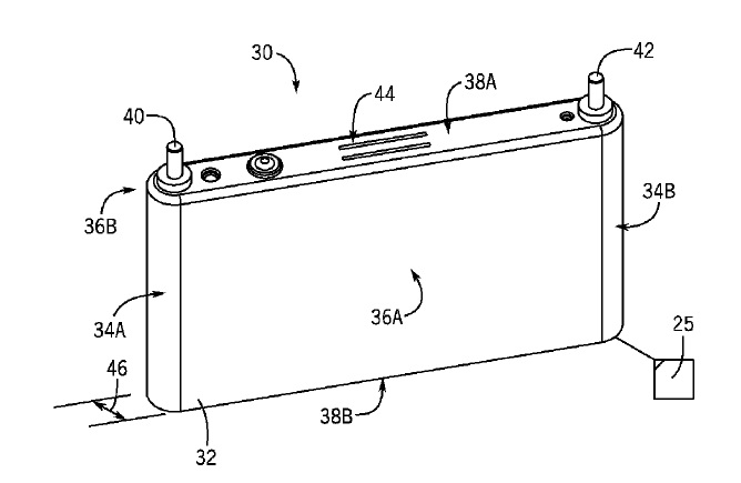
US10199695 — BATTERY MODULE WITH RESTRAINED BATTERY CELLS UTILIZING A HEAT EXCHANGER — Johnson Controls Technology Company (USA) — A battery module includes a battery module housing, a heat exchanger including a plurality of fins disposed in the housing, a first lithium ion battery cell and a second lithium ion battery cell disposed within the battery module housing. The first lithium ion battery cell and the second lithium ion battery cell are separated by a fin of the plurality of fins. The module includes a temperature sensing component coupled to the fin separating the first and second battery cells. Filler material is disposed within the housing and between the battery cells and the fins to mechanically restrain the battery cells within the battery module housing. The filler materials conduct thermal energy between the battery cells and the fin. The filler material covers a free end of the fin and the temperature sensing component. The temperature sensing component is coupled to a conductor extending out of the filler material. For embodiments in which the prismatic battery cells 30 include an embodiment of the positive terminal 40 made from a first metal (e.g., aluminum) and an embodiment of the negative terminal 42 made from a second metal (e.g., copper), a portion of each bus bar 50, 52 may be made from the first metal (e.g., aluminum), and another portion may be made from the second metal (e.g., copper) to enable effective laser welding and mitigate galvanic effects.
US10199676 — SECONDARY BATTERY PACK COMPRISING MOVABLE WALL AND ELASTIC MEMBER — SK Innovation Co., Ltd. (Korea) — A secondary battery pack including end plates capable of suppressing a deformation caused by an expansion force of unit cells, a movable wall consisting of an aluminum die casting disposed between at least one end plate and one side face of a unit cell, elastic members disposed between at least one end plate and the movable wall, and connecting bars configured to connect the end plates with each other disposed on both opposite end sides of the at least one unit cell.
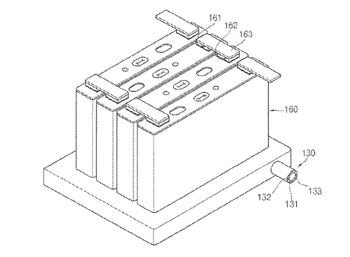
US10193126 — BATTERY TERMINAL, METHOD FOR MANUFACTURING BATTERY TERMINAL, AND BATTERY — Hitachi Metals, Ltd. and Aoyama Seisakusho Ibaraki Plant Co., Ltd. (Japan) — A battery terminal includes a shaft portion and a flange portion. The battery terminal is made of a clad material in which at least a first metal layer and a second metal layer are bonded to each other. The battery terminal according to the first aspect, one of the first metal layer and the second metal layer is preferably made of Al or an Al alloy (Al-base alloy), and the other of the first metal layer and the second metal layer is preferably made of Cu or a Cu alloy (Cu-base alloy). Each of the shaft portion and the flange portion includes the first metal layer on a first side in a shaft direction and the second metal layer on a second side in the shaft direction. The first metal layer in the shaft portion includes a protruding portion that further protrudes to the second side in the shaft direction with respect to a surface of the first metal layer on the second side in the shaft direction in the flange portion. Bus bars of Al are employed, whereby the weight of the bus bars can be reduced so that the weight of the entire assembled battery employing the plurality of bus bars can be reduced, as compared with the case where bus bars of Cu are employed.
US10193123 — BATTERY PACK BUS BAR ASSEMBLY WITH ENLARGED INTERCONNECT MOUNTING PLATFORMS — Atieva, Inc. (USA) — A battery assembly utilizing a compact and robust bus bar configuration is provided. The batteries within the assembly are divided into groups, for example where each group is formed from two rows of batteries. The batteries within each battery group are connected in parallel and the groups are connected in series. The batteries are interconnected using a plurality of non-overlapping bus bars configured in an alternating pattern with the plurality of battery groups, where each of the bus bars includes multiple interconnect mounting platforms. The interconnect mounting platforms simplify coupling multiple rows of batteries to each bus bar while minimizing bus bar current density variations and insuring that individual interconnect resistance remains relatively low and at about the same level per battery. Bus bars are preferably made of copper, although other suitable electrically conductive materials such as aluminum may be used.
US10192807 — POWER SEMICONDUCTOR MODULE, FLOW PATH MEMBER, AND POWER-SEMICONDUCTOR-MODULE STRUCTURE — Fuji Electric Co., Ltd. (Japan) — The invention is provided with a metal base plate including a first surface and a second surface and a cooling case including a bottom wall and a side wall formed around the bottom wall, in which one end of the side wall being joined to a second surface side of the metal base plate, and a coolant can be circulated in a space enclosed by an aluminum alloy base plate, the bottom wall, and the side wall, in which the cooling case has an inlet portion and an outlet portion for the coolant which are connected to either the bottom wall or the side wall and disposed along a peripheral edge of the second surface of the aluminum alloy base plate, and includes a first flange disposed at an inlet opening side of the inlet portion and a second flange disposed at an outlet opening side of the outlet portion.
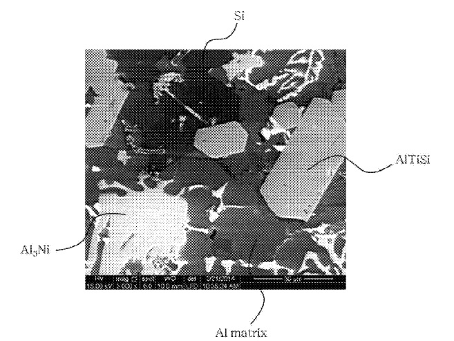
US10190535 — HYPEREUTECTIC ALUMINUM-SILICON-BASED ALLOY HAVING SUPERIOR ELASTICITY AND WEAR RESISTANCE — Hyundai Motor Company (Korea) — Disclosed is an aluminum alloy having superior elasticity and wear resistance. The aluminum alloy has superior elasticity and wear resistance and improved wear properties by including additional reinforcing phase formation such as Al3Ni phase formation. In particular, the reinforcing phase may be generated by adding nickel (Ni) that may reinforce and enhance properties which may be decreased due to generation of a ternary phase such as TiAlSi. The aluminum alloy comprises an amount of about 13 to 21% by weight of the silicon (Si), an amount of about 1 to 5% by weight of the nickel (Ni), an amount of about 4 to 5% by weight of the titanium (Ti), an amount of about 0.7 to 1% by weight of boron (B), and a remainder of Al based on a total weight of the aluminum alloy. This alloy is suitable for vehicle components that comprise the aluminum alloys as described herein, in particular, vehicle parts such as a cylinder block or a cylinder block in an internal combustion engine of the vehicles may comprise the aluminum alloys as described herein and includes hybrid vehicles, electric vehicles, plug-in hybrid electric vehicles, hydrogen-powered vehicles and other alternative fuel vehicles (e.g. fuels derived from resources other than petroleum).
US10189422 — WIRE HARNESS — Yazaki Corporation (Japan) — A wire harness, which is laid out on a hybrid electric vehicle (or an electric vehicle), electrically connects high-voltage devices includes a conductive path that is used as a trunk cable, a branch cable that branches from the trunk cable, and a branch connecting portion which connects the trunk cable with the branch cable, wherein the trunk cable has a trunk cable-side conductor exposed portion where a cover of the trunk cable lying in a predetermined position of the trunk cable is removed, the branch cable has a branch cable-side conductor exposed portion where a cover of the branch cable lying a predetermined position of the branch cable is removed, the trunk cable-side conductor exposed portion is connected with the branch cable-side conductor exposed portion at the branch connecting portion, and the branch connecting portion has an insulating and waterproofing portion which functions as an insulating portion and a waterproofing portion. In this embodiment, aluminum conductors are adopted since the aluminum conductors are advantageous in cost and weight; the aluminum conductors are inexpensive, and light (the adoption of the aluminum conductors is only an example).
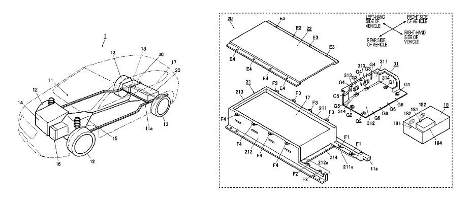
US10189371 — ELECTRICALLY-POWERED VEHICLE — Subaru Corporation (Japan) — An electrically-powered vehicle includes a high voltage battery, a charger, and a battery case. The high voltage battery stores electric power for travelling. The charger is enclosed in an aluminum alloy housing and outputs charge current to the high voltage battery. The battery case accommodates the high voltage battery. The battery case includes a low stiffness material member that covers one side of the high voltage battery in a horizontal direction and that is formed of a material having stiffness lower than stiffness of a portion that covers the other side in the horizontal direction. The low stiffness material member, which may be an aluminum alloy, and the charger are fastened to each other at different locations in the horizontal direction.
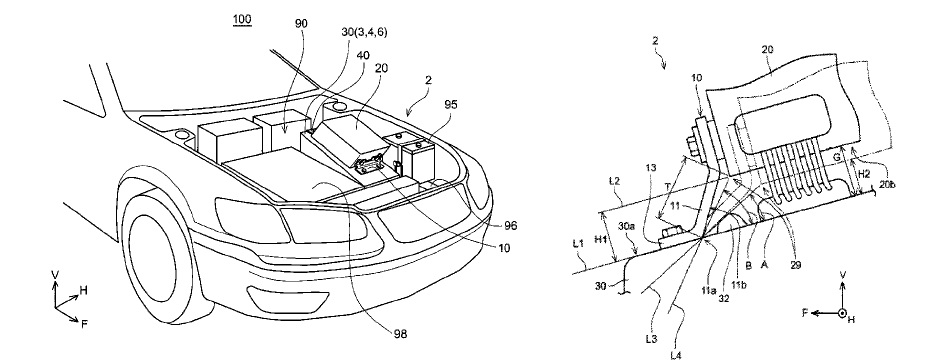
US10189353 — ON-VEHICLE STRUCTURE — Toyota Jidosha Kabushiki Kaisha (Japan) — An on-vehicle structure includes am aluminum alloy housing of a motor and a power control unit. The power control unit is fixed by a front bracket and a rear bracket above the housing. A space is defined between a lower surface of the power control unit and the housing. The front bracket includes a base section and a support section. The support section is configured to contact with the housing before the lower surface of the power control unit contacts with an upper surface of the housing when the support section is collapsed rearward by a load applied to the power control unit from front.
US10186737 — TRACTION BATTERY INTEGRATED THERMAL PLATE AND TRAY — Ford Global Technologies, LLC (USA) — A vehicle traction battery assembly may include a traction battery and a battery tray. The traction battery is for powering a portion of an electrified vehicle. The battery tray is for supporting the traction battery and defines a coolant channel for distributing coolant in a first direction and a second direction. Battery cells of the traction battery are arranged with the battery tray such that the first direction and the second direction are oriented perpendicular relative to a longitudinal face of one of the battery cells. A plate may be secured to the battery tray without mechanical fasteners to retain coolant within the coolant channel. The plate may be made of aluminum and the battery tray may be die cast aluminum. An inlet channel may extend from an inlet to the coolant channel and may be disposed between a pair of openings defined by the battery tray.
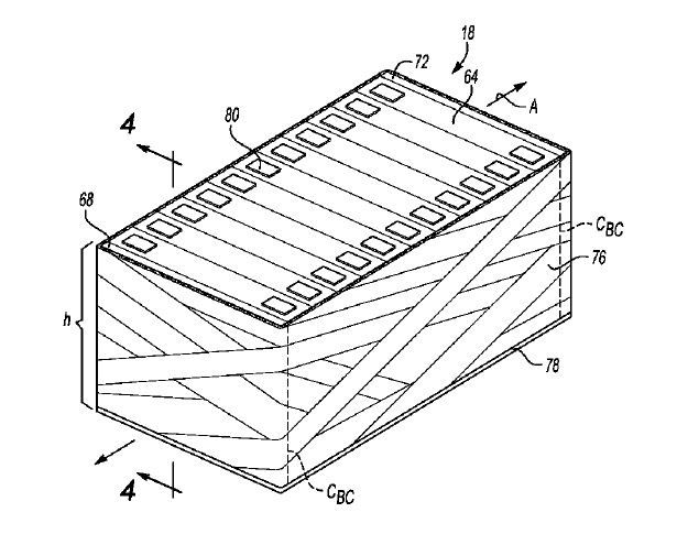
US10186729 — BATTERY CELL COMPRESSION METHOD AND ASSEMBLY — Ford Global Technologies, LLC (USA) — An exemplary method includes, among other things, winding a curable material at least partially about a plurality of battery cells that are compressed by a fixture. An exemplary assembly includes, among other things, a plurality of battery cells compressed by a fixture, and a curable material wound around plates comprising the plurality of battery cells. The plates are a metal or metal alloy. In particular, the plates could be extruded aluminum.
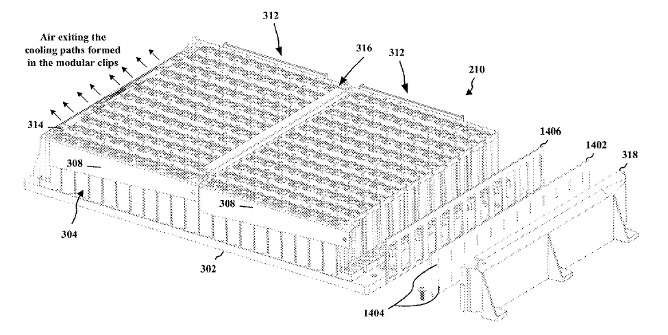
US10186697 — BATTERY MODULE WITH COOLING ASPECTS — Thor Trucks Inc. (USA) — Aspects of a modular clip for an electric battery, a battery module comprising multiple such modular clips, and a battery pack comprising multiple battery modules mounted on a base plate are provided. The modular clip includes a housing configured to receive a plurality of battery cells. The housing includes a base portion and a first and second wall extending from the base portion of the housing along a length of the housing, wherein the plurality of battery cells are received between the first wall and the second wall. The first and/or second wall forms a cooling path along the length of the housing, e.g., a gap maintained between the plurality of cells and the first/second wall. The battery module may include a regulator and duct to direct/control air flow to the cooling path in each of the modular clips comprised in a battery module. The base plate 302 may be a die cast or machined aluminum alloy.
US10178805 — HEATSINK WITH INTERNAL CAVITY FOR LIQUID COOLING — Tesla, Inc. (USA) — A heatsink with an internal cavity for liquid cooling includes: a first part having a first group of fins extending into the internal cavity; a second part attached to the first part so that the internal cavity is formed, the second part having a second group of fins that extend into the internal cavity and that are configured to fit among the first group of fins; an inlet into the internal cavity on at least one of the first and second parts; and an outlet from the internal cavity on at least one of the first and second parts which are made of aluminum.
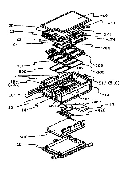
US10178780 — POWER CONVERSION APPARATUS AND ELECTRIC VEHICLE — Hitachi, Ltd. (Japan) — The metallic case of a power conversion apparatus includes a casing having a side wall, as well as an upper case and a lower case, a first area being formed between a cooling jacket provided at the inner periphery of the side wall and the lower case, the metal base plate dividing the first area between the cooling jacket and the upper case into a lower side second area and an upper side third area, first and second power modules being fastened to a top surface and a capacitor module being provided in the first area, driving circuits that drive inverter circuits of the power modules respectively being provided in the second area, and a control circuit that controls the driver circuits being provided in the third area. The power conversion apparatus 200 can thus be cooled down at a smaller space, thereby the apparatus 200 can be reduced in total size. And because the cooling jacket 19A and the apparatus casing 12 are united into one by aluminum casting, the cooling jacket 19A can be improved in cooling efficiency and in mechanical strength. This aluminum casting, which enables the apparatus casing 12 and the cooling jacket 19A to be united into one, can also improve the thermal conductivity, so that it is possible to improve the cooling efficiency of the driving circuit board 22, the control circuit board 20, and the capacitor module 500 disposed farther from the cooling jacket 19A.
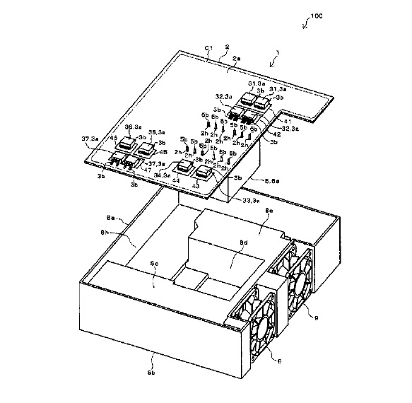
US10178754 — CIRCUIT BOARD MODULE AND ELECTRONIC DEVICE — Omron Automotive Electronics Co., Ltd. (Japan) — A circuit board module includes: a first electronic component of a surface mounting type; a second electronic component of an insertion mounting type including a lead terminal; a circuit board; and a heat transfer body provided in the circuit board. A case 8a and a heat sink 8b are integrally formed of aluminum having heat radiation properties. The first electronic component is mounted on a front surface of the circuit board so as to overlap the heat transfer body in a board thickness direction. The heat transfer body is provided so as to transfer heat generated in the first electronic component to a back surface side of the circuit board. The second electronic component is mounted on a back surface of the circuit board. The second electronic component and the heat transfer body are thermally connected to a heat radiation body provided on the back surface side of the circuit board.
US10177411 — NONAQUEOUS ELECTROLYTE SECONDARY BATTERY AND METHOD OF MANUFACTURING THE SAME — Toyota Jidosha Kabushiki Kaisha (Japan) — A nonaqueous electrolyte secondary battery includes: a wound electrode body that is formed by laminating an elongated sheet-shaped positive electrode current collector foil, an elongated sheet-shaped negative electrode current collector foil, and an elongated sheet-shaped separator to obtain a laminate and winding the obtained laminate; a nonaqueous electrolytic solution; and an aluminum case that accommodates the wound electrode body and the nonaqueous electrolytic solution. In this kind of nonaqueous electrolyte secondary battery, aluminum foil is generally used as a positive electrode current collector foil. In the wound electrode body including the positive electrode current collector foil that is aluminum foil having an overall arithmetic average roughness of 0.08 μm to 0.12 μm. A solid electrolyte interface film derived from an oxalato borate complex is formed on at least a surface of the negative electrode active material layer.
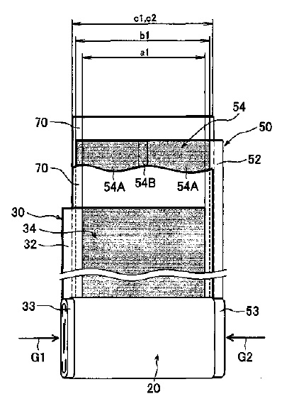
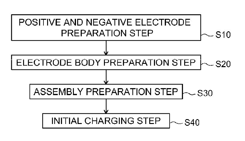
US10177408 — NON-AQUEOUS ELECTROLYTE SECONDARY BATTERY AND METHOD FOR PRODUCING SAME — Toyota Jidosha Kabushiki Kaisha (Japan) — The non-aqueous electrolyte secondary battery 10 according to the present invention is provided with an electrode body 50 including a positive electrode 64 that contains a positive electrode active material and a negative electrode 84 that contains a negative electrode active material, a non-aqueous electrolyte, and an aluminum battery case 15 that houses the electrode body and the non-aqueous electrolyte. In the same way as positive electrode current collectors able to be used in a positive electrodes of conventional lithium ion secondary batteries, aluminum and alloys made mainly of aluminum can be used as the positive electrode current collector. The non-aqueous electrolyte contains a complex, which contains copper (I) chloride as a constituent component and which is capable of adsorbing at least carbon monoxide and carbon dioxide, and a coating film that contains at least one of phosphorus and boron is formed on the surface of the negative electrode active material.
US10177353 — RECHARGEABLE BATTERY MODULE — Samsung SDI Co., Ltd. (Korea) — A rechargeable battery module is disclosed. In one aspect, the battery module includes a plurality of unit cells including first and second outermost unit cells disposed at first and second opposing ends of the unit cells arranged in a first direction, wherein the unit cells have top and bottom surfaces opposing each other. The battery module also includes a bus bar holder covering the top surface of the unit cells, a bus bar disposed at the bus bar holder to electrically connect the unit cells and a pair of end plates respectively supporting the first and second outermost unit cells. The battery module further includes a pair of side plates disposed at third and fourth opposing ends of the unit cells arranged in a second direction crossing the first direction, wherein the side plates are connected to the end plates and the bus bar holder.
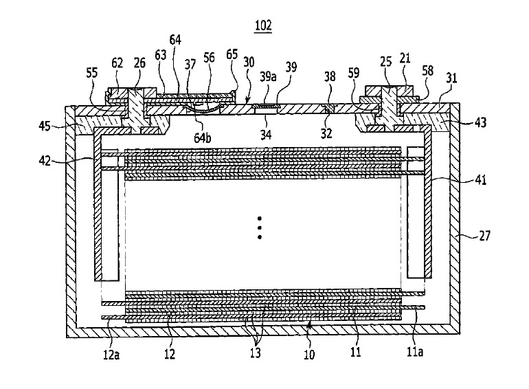
US10177348 — NONAQUEOUS ELECTROLYTE SECONDARY BATTERY AND PACK BATTERY — Toyota Jidosha Kabushiki Kaisha (Japan) — A nonaqueous electrolyte secondary battery, wherein the positive electrode current collector is made of aluminum, and the negative electrode current collector is made of copper, includes a wound electrode body housed in a battery case. The wound electrode body is positioned to the battery case with a positioning member. Among a spatial volume excluding the wound electrode body in the battery case, in a direction of a winding axis of the wound electrode body, a spatial volume X on a negative electrode side of the battery case is larger than a spatial volume Y on a positive electrode side of the battery case. Here, the spatial volume X and the spatial volume Y satisfy 2.1<(X/Y)<5.7. The battery case body and sealing plate are made of an aluminum alloy.
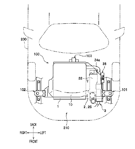
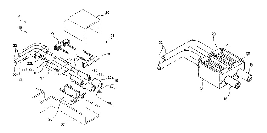
US10170865 — SHIELDED ELECTRIC WIRE CONNECTION STRUCTURE — Toyota Jidosha Kabushiki Kaisha, Sumitomo Wiring Systems, Ltd., Autonetworks Technologies, Ltd., And Sumitomo Electric Industries, Ltd. (Japan) — The electric shielded wire connection structure includes: a lower side case made of an aluminum alloy that accommodates a rotary electric machine; an upper side case that is positioned immediately above, and facing, the lower side case and accommodates an inverter; a plurality of electric wires that is arranged in a state where one end thereof is connected to a lower side terminal block immediately under the upper side case, the other end thereof is connected to an upper side terminal block at a wall surface side end part of the upper side case, and the plurality of electric wires is bent from the position immediately under the upper side case so as to face the wall surface; and a braided shielding member that shields the plurality of electric wires and is arranged for the plurality of electric wires only at the side opposite to the surface facing the upper side case.
US10170808 — BATTERY PACK — Samsung SDI Co., Ltd. (Korea) — A battery pack including a plate-shaped aluminum cooling plate of high conductivity; a plurality of battery modules, the plurality of battery modules being mounted on a top surface of the cooling plate; and at least one bracket on one lengthwise side of the cooling plate.
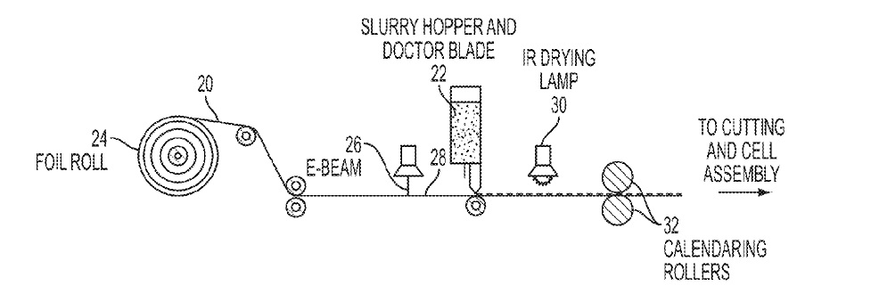
US10170747 — TREATED CURRENT COLLECTOR FOIL — Ford Global Technologies, LLC (USA) — In at least one embodiment, a battery is provided comprising an electron beam-treated current collector made of aluminum or copper foil having an increased surface energy compared to an untreated current collector and an electrode disposed on a treated surface of the current collector. The electrode may include a water-soluble binder uniformly coating a surface of the current collector and the treated current collector may have a contact angle with the water-soluble binder of 70 degrees or less. The electron beam treatment may be applied to a moving current collector foil as part of a battery production process, prior to application of an electrode slurry.
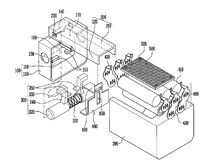
US10170736 — BATTERY CASE — Samsung SDI Co., Ltd. (Korea) — A battery case is disclosed. In one aspect, the battery case includes a front case and an attaching/detaching mechanism. The front case includes a first surface corresponding to a front end portion of a battery module placed in parallel to a bottom surface thereof, and a first flange portion extending toward the battery module from the periphery of the first surface, the first flange portion having an opening formed in an upper surface thereof. The attaching/detaching mechanism includes an elastic member positioned between the front case and a front end portion of the battery module, cover members respectively surrounding both ends of the elastic member, an extending member extended upward from one area of each cover member, and a press member respectively formed toward both the ends of the elastic portion at end portions of the extending member. The battery case further comprising a rear case at least partially formed of an aluminum material configured to surround the battery module, the rear case being couple to the front case and the top case.
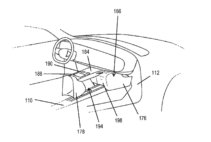
US10166929 — STORAGE BOX — Thunder Power Electric Vehicle Limited (China) — A storage area for an electric vehicle includes a rigid tunnel positioned within a passenger compartment of the electric vehicle. The tunnel covers a portion of a battery assembly that extends above a floor structure of the vehicle such that the passenger compartment is sealed from the battery assembly. A center console is positioned within the passenger compartment. The center console is disposed on top of the tunnel such that a medial portion of the center console is spaced a vertical distance above a top surface of the rigid tunnel. A first end and a second end of the center console are coupled with the top surface of the rigid tunnel. A thickness of the medial portion is less than that of the first end and the second end. A space between the top surface of the tunnel and a bottom surface of the medial portion defines the storage area. Here, much of the main body of the electric vehicle, especially those components designed to form the skeleton of the vehicle and those components used for collision protection, are made of aluminum or alloys containing aluminum. Battery elements are positioned underneath a floor structure of the electric vehicle. Such positioning provides several benefits. First, the battery elements are isolated from the passenger compartment, largely by an aluminum floor structure, which helps increase passenger safety.
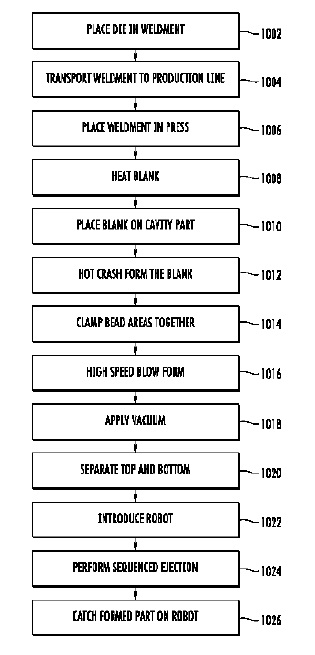
US10166590 — HIGH SPEED BLOW FORMING PROCESSES — Tesla Motors, Inc. (USA) — A method of forming a part from aluminum includes: inserting a blank into a die, the die comprising a mold mounted above a sealing counterpart; clamping the blank between the mold and the sealing counterpart; applying first pressure on the blank from the sealing counterpart so the blank is pressed upward to form a shaped part corresponding to the mold; applying a vacuum to the shaped part to hold it against the mold also after separating the mold and the sealing counterpart, the vacuum applied through at least one opening in the mold located in a corner of the mold that the blank does not reach when the first pressure is applied; and discontinuing the vacuum to allow the shaped part to be released from the mold.
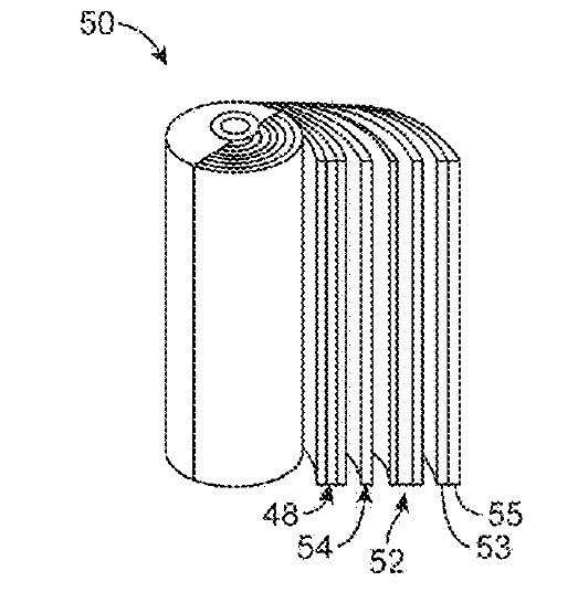
US10164304 — THERMALLY DISSIPATIVE ELECTROCHEMICAL CELL — The United States of America, as represented by the Secretary of the Navy (USA) — According to exemplary practice of the present invention, a cylindrical secondary electrochemical cell (e.g., lithium-ion cell) includes a disk that is made of a thermally and electrically conductive material (e.g., aluminum), and that lies in a geometric plane that is perpendicular to the cylindrical axis. The disk is adjacently intermediate, axially aligned with, and electrically connected to two cylindrical jelly-roll electrode components. Inventive practice is possible with respect to a variety of cell types, shapes, and chemistries. Depending on the inventive embodiment, the numbers of disks (≥1) and jelly-roll electrode components (>2) can vary, each disk serving to augment heat transport in the radial direction. An inventive cylindrical cell thus affords superior heat spreading in the direction radially outward, 360 degrees, from the central axis of the cell.
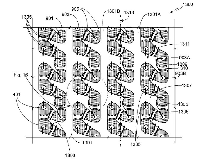
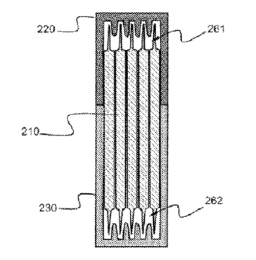
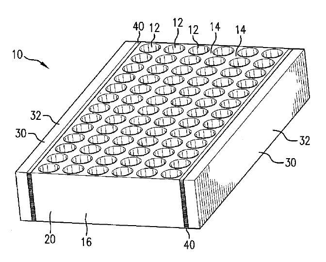
US10164301 — ENERGY STORAGE THERMAL MANAGEMENT SYSTEM USING MULTI-TEMPERATURE PHASE CHANGE MATERIALS — All Cell Technologies, LLC (USA) — A thermal management method and system for energy storage devices, such as devices including an array of electrochemical cell elements. A first phase change material is in heat-transferring thermal contact with the electrochemical cell elements. A second phase change material in heat-transferring thermal contact with the first phase change material. A heat exchange path can be disposed between the first phase change material and the second phase change material. The containment lattice member 20 is desirably formed of a heat-conductive material such as of metal, graphite or a composite thereof, for example. Preferred containment lattice member materials for use in the practice of the invention include, for example, various screen and foam materials such as graphite foam and metal foams such as aluminum foam and particularly open-celled forms of such foams.
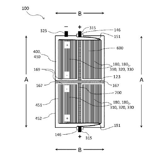
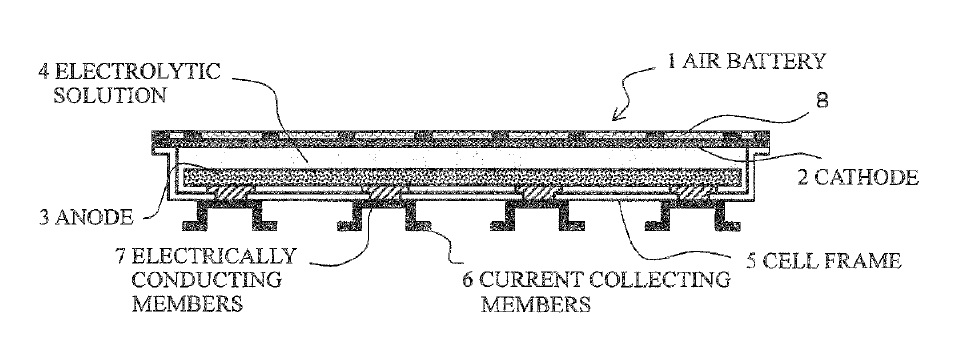
US10164237 — AIR BATTERY CELL WITH ELECTRICALLY CONDUCTIVE MEMBERS AND BATTERY PACK — Nissan Motor Co., Ltd. (Japan) — An air battery includes: a cell frame of an insulating material having a bottomed frame shape in which an electrolytic solution and an anode are stored; a cathode that is disposed opposite the anode across the electrolytic solution stored in the cell frame; and a current collecting member that is electrically connected to the anode, wherein the anode and the current collecting member are electrically connected to each other via a plurality of electrically conducting members that penetrate a bottom of the cell frame. The anode is made of a pure base metal that has a standard electrode potential less than hydrogen, or an alloy of such a metal. Such pure metals include, for example, zinc (Zn), iron (Fe), aluminum (Al), magnesium (Mg) and the like. The current collecting members 6 are desirably made of a highly electrically conductive metal, particularly copper, aluminum or the like.
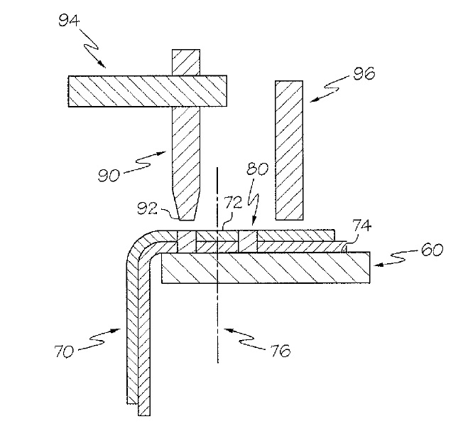
US10158114 — ONE-SIDED ULTRASONIC BONDING FOR APPLICATIONS TO JOIN BATTERY TABS TO BUS BARS — GM Global Technology Operations LLC (USA) — A method of ultrasonically bonding a plurality of prismatic battery cell tabs to a bus bar within a battery section, wherein the plurality of cell tabs and the bus bar are made of a material that can be made from aluminum or aluminum alloys. The method includes arranging numerous prismatic battery cells such that cell tabs that extend from their lateral edge are substantially aligned along a stacking dimension defined within the battery section and positioning a free end of at least one of the plurality of cell tabs in contact with a surface of the bus bar. The method is completed by contacting a bonding tool to no more than one surface of the positioned cell tab free end and ultrasonically bonding the positioned cell tab free end to a bus bar with the bonding tool. The one-sided bonding tool has a bonding tip cooperative with an ultrasonic excitation source.
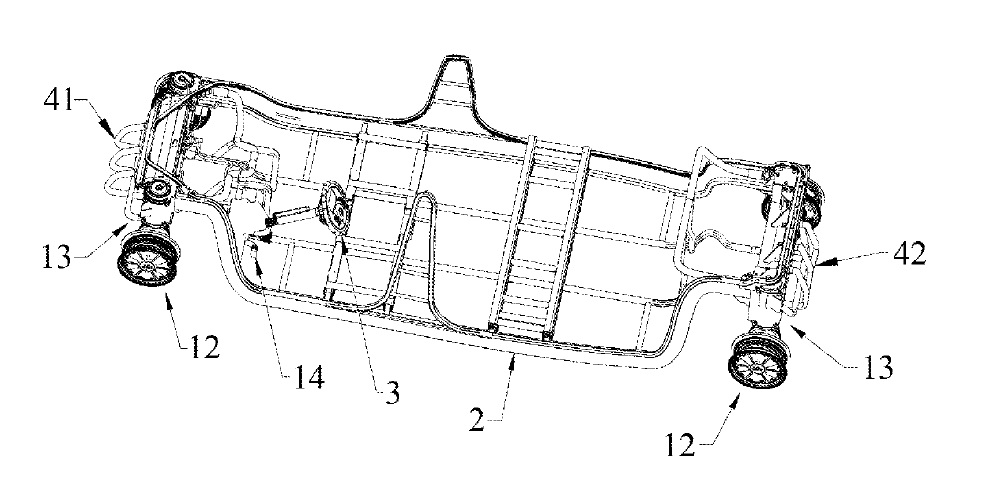
US10155442 — ELECTRIC VEHICLE CHASSIS AND ELECTRIC VEHICLE USING SAME — Shenzhen Zhilun Driving Technology for Electric Vehicle Co., Ltd. (China) — Disclosed are an electric vehicle chassis and an electric vehicle using the electric vehicle chassis. The electric vehicle chassis comprises a frame system (2), a steering motor damping system (13), a wheel system (12), a steering system (3) and a braking system (14), wherein the wheel system (12) comprises a left front wheel (121) using a hub motor, a left rear wheel (123) using a hub motor, a right front wheel (122) using a hub motor, and a right rear wheel (124) using a hub motor; and the steering motor damping system (13) comprises a left front steering damping motor (131), a right front steering damping motor (133), a left rear steering damping motor (135) and a right rear steering damping motor (137). The frame system comprises two multi-cavity box stringers spaced and symmetrically placed and made of aluminum alloy and a multi-cavity beam assembly made of aluminum alloy. Driving the wheels with the hub motors can omit a traditional mechanical transmission system, so as to simplify the structure of the chassis, reduce the weight of the chassis, and also reduce the mechanical transmission loss, thereby improving the power utilization efficiency.
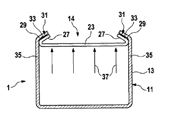
US10135039 — BATTERY CELL COMPRISING A COVERING PLATE FIXED IN A FORM-FITTING MANNER IN A HOUSING — Robert Bosch GmbH (Germany) — The invention relates to a battery cell (1), in particular a lithium ion battery cell, in which a wrapping element, two current collectors and an electrolyte are accommodated in a housing (11). The battery cell 1 has a coil element 3 comprising a wound stack 5 comprising a copper film, which is coated with anode material, and an aluminum film, which is coated with cathode material, and plastic films therebetween, which act as diaphragms. For electrical contact-making, the copper film and the aluminum film are stacked one on top of the other with a slight offset along the coil axis in the opposite direction so that the copper film on a narrow side and the aluminum film on an opposite narrow side protrude slightly beyond a respective rim of the coil element. A copper current collector 7 is welded to a protruding region 4 of the copper film so that this current collector is electrically connected to the anode of the coil element. An aluminum second current collector 9 is welded to an opposite protruding region of the aluminum film in order to produce electrical contact with the cathode of the coil element 3. The prismatically formed housing (11) comprises a container that is open towards the upper side and a cover arrangement having a cover plate (23) closing the opening (14) of said container. The cover plate (23) and a wall of the container (13) are designed in the region of the opening (14) in such a manner that the wall prevents a movement of the cover plate (23) from the opening by means of a positive connection. An elastically compressible sealing element (31) is provided between the wall and a wall surface of an outer edge (27) of the cover plate directed towards said wall, in order to seal the cover plate (23) hermetically against the container (13). On the basis of the positive connection between the cover plate (23) and the edge of the container (13) a sealing effect can hereby likewise increase while the inner pressure in the housing (11) increases.