By Ken Chien and Paul Robbins, Castool; Chris Jowett, Rio Tinto Aluminium;
and Yu Wang, Mechanical and Mechatronics Engineering Dept., University of Waterloo
Introduction
When extruders decide to install a new press they naturally consider the product mix and profile size and weight (lb/ft). Depending on the run-out table, this determines the ideal billet weight. They choose a press tonnage usually based on the billet diameter and the requirement of a certain dummy block pressure. Maximum extrusion speed is achieved when pushing the coldest possible billet, in other words when the press load is at a maximum at breakthrough. With that requirement, all that is needed for high productivity are pumps that can deliver a high ram speed.
One additional question, which is the subject of this paper, is what is the best billet geometry? This question is concerned with a geometry (combination of diameter and length) that minimizes the press force and therefore allows billet temperature to be minimized and extrusion speed maximized. Large profiles that naturally benefit from a large container are not specifically being considered in this case.
Another question is if a press has a certain geometry and there is a need to increase billet weight, what is the best direction? Clearly, increasing billet length could achieve this, but it is certain that this also increases the press force, requiring an increase in billet temperature and a lowering in speed. On the other hand, the container diameter could be increased, which achieves exactly the same result. But does it? It is certainly important that one should not blindly increase billet length or billet diameter and expect improved productivity, especially if this creates problems with other parts of the process, such as: dummy block functioning, extrusion dimensions, butt shearing, metal flow, etc. Increasing billet weight will likely increase contact utilization, but it might not increase productivity; it might do the opposite. This is the subject that is addressed in this series of papers.
Short Versus Long Billets
In recent years, we have seen a trend toward longer containers, which allow billets that are as much as eight times longer than the diameter, rather than what typically used to be a 5 to 1 ratio. Many extruders are tending to move to longer billets. Some of these extruders are seeing improvements in productivity with better contact utilization, while others are seeing the opposite. Many report higher contact utilization with long billets and perhaps assume that this means higher productivity. With the more common use of front-loading presses, it is now simple to increase the maximum billet length. Clearly extruders producing coiled product might prefer longer billet lengths at lower speed. For regular extruders, it is not immediately obvious which is the best option allowing the highest extrusion productivity.
Breakthrough Force and Pressure
If we want to compare the breakthrough pressure of short billet versus long billet, one of the formulas to use would be:
Pressure = A log (Extrusion Ratio) + B (alloy shear stress x liner surface area)
The first term represents the part of the force that goes to reducing the billet to the profile. The second term calculates the force to overcome shearing of the billet as the metal moves through the container. With the complication of the temperature rise through heat of deformation, this is more accurately calculated by Finite Element (FE) modeling.
We have modeled the extrusion of billets with different geometries using the DEFORM 2D® finite element package at the University of Waterloo, Ontario. For a starting point, we chose two billet dimensions, the first an 8 inch diameter with a length of 56 inches with an aspect ratio of 7:1 (which is typical of the modern trend to longer billets). The other was a 10 inch diameter with a length of 35.8 inches and an aspect ratio of 3.5:1. Both billets weigh 276 lbs or have a volume of 2,815 cubic inches. The die was a round bar with a diameter of 1.275 inches to simplify the simulation. The initial modeling was with alloy AA6063 at a temperature of 850°F. Ram speed for the 10.375 inch liner was 0.453 inches/sec and for the 8.375 inch liner, 0.6953 inches/sec. This resulted in identical extrusion speeds of 150 ft/min. The model aims to provide insights into the productivity possible with different billet geometries.
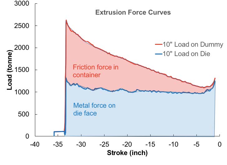
A typical load/stroke plot for the 10 inch billet at 850°F is shown in Figure 1. The upper curve shows the press load on the stem and the lower curve the force on the die. While the die load is relatively constant throughout the stroke, there is a slight drop in force caused by increasing temperature during the push. Figure 2 shows loads on the dummy block for 8 inch and 10 inch billets at 800°F and 850°F. The observation is that the force on the dummy block is very similar with both the 10 inch x 35.8 inch and 8 inch x 56 inch billet geometries (Table I).


When comparing the different billet diameters for a temperature of 850°F, the 10 inch requires 1.9% more load and, for 800°F billets, 1.8% more. This data suggests that in order to achieve an identical extrusion load would mean an increase of only 7°F in the 10 inch billet temperature.
This observation that the press load is effectively the same with the two billet geometries is interesting as the difference in billet geometries is extremely large. It would suggest that a requirement to add billet weight can be done equally by increasing the billet diameter or the billet length. The first option is superior as this can be done by simply replacing tooling. There is a limit set by the press frame as to how much you can increase the billet length.
Temperature and Speed
As with the press load calculations, there is little difference in temperature with the 8 inch and 10 inch set-ups. These are shown in Figure 3. Here, the temperature of the die bearing is higher at the start with the 10 inch billet, while at the end it is the 8 inch that runs hotter.
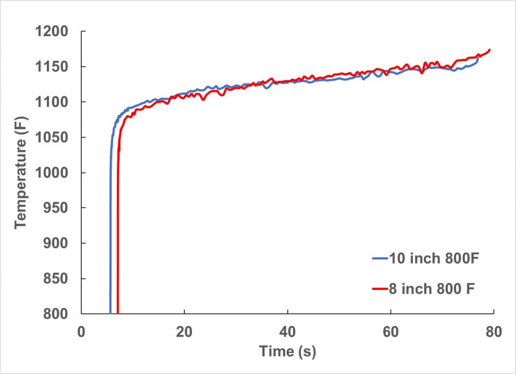
Figure 4 shows the temperature change of the metal as it flows through the container and die. The tendency of the metal to warm up as it flows through the container is greater with the long 8 inch billet. With the very rapid heating as the billet is reduced in size approaching the die, the heating is greatest with the 10 inch billet (higher reduction ratio). The combination of these different heating patterns results in an almost identical die temperature (see Figure 4 insert). We can say there is no benefit on one over the other—as far as extrusion temperature is concerned.
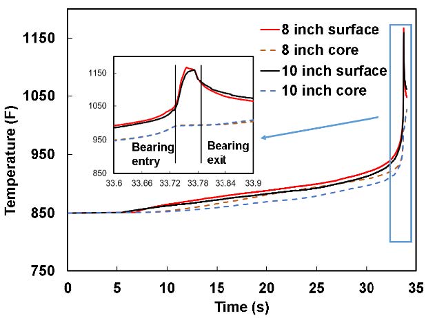
The similarity between the data is quite clear. Since, the temperatures are almost the same for 10 inch and 8 inch billets, extruders can choose either without any measurable difference in press performance. We consider this to be an intriguing and possibly surprising result offering options to the extruder.
Container Cooling and Taper
Modeling of the effect of billet/container temperature differential is illustrated in Figure 5, which shows the die bearing temperature with an 8 inch billet of 800°F and 850°F and 850°F with an 800°F container.
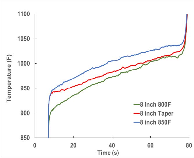
At the start of extrusion, as one might expect, the temperature is characteristic of the billet, but throughout the extrusion the temperature reduces to what one would expect with an 800°F billet. One could imagine that with a larger differential we could approach isothermal extrusion. An equally predictable result is seen in the press load. At breakthrough it is characteristic of the hot billet (that is low) and changes to that resulting from the cold liner at which point it is irrelevant because of the available pressure.
These simple observations suggest that the container should always be at least 50°F cooler than the billet, from the point of view of productivity as well as the well-known effect of reducing billet skin flow into the profile. The controlling factor with this is the ability to maintain this temperature differential, something that is best achieved with a smart container with high conductivity steel and cooling fans on the exterior.
Pressure on Dummy Blocks and Dummy Block Design
Regarding the functioning of the dummy block, the pressure in the container and on the dummy block and stem is far lower with the 10 inch billet than the 8 inch. The breakthrough pressure for the 10 inch billet is calculated as 77 ksi compared with 118 ksi for the 8 inch. The pressure at the end of the stroke is approximately 30 ksi for both sizes. The simulation in Figure 6 shows the stress inside the dummy block at pressures of 100 ksi and 120 ksi. The red areas show stresses higher than the yield strength of H13 (156,000 psi) and those areas will start to plastically deform or creep first. This work was reported at ET 2016. For long extrusion runs, the dummy block needs to be designed carefully to handle pressures higher than 100 ksi. Normally the dummy block is made of H13 due to its high tensile strength and toughness at extrusion temperature. One alternative is to use a better material for this application, such as Tuff Temper, which was developed to handle this situation. Comparative properties are shown in Table II. The impact toughness is also higher than H13, which provides good thermal shock resistance. Tuff Temper heat treated to 48HRc has the same or better toughness than H13. The impact toughness of H13 is about 7 ft-lb and for high quality H13 is about 10 ft-lb. The impact toughness of Tuff Temper is about 10 ft-lb.


Aluminum Skin Thickness
One problem that has occurred with longer billets is the difficulty in designing a dummy block that works. This is because the force varies so dramatically from front to back, perhaps starting with a specific pressure of 120 ksi reducing to 30 ksi. Since the expansion of the dummy block solely relies on pressure, this becomes an extremely difficult problem if the objective is a uniform thin skull on the liner wall. If the skull varies in thickness front-to-back then quality and recovery will suffer. A lower specific pressure with the 10 inch billet is a huge advantage to good functioning of the block.
Container Design for Long Billets
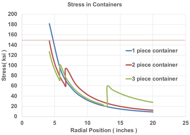
The container under extrusion pressure acts as a thick cylinder with internal pressure. Extrusion pressure is maximum at breakthrough and reduces through the extrusion cycle by as much as 50%. The stress is highest near the liner ID surface and lowest near the container OD surface. Figure 7 shows the rule of thumb for the stress on the liner ID surface. In a one-piece container, it is about 1.8 times the dummy block face specific pressure, in a two-piece container about 1.5 times, and in a three-piece container about 1.3 times.
With the 100 ksi pressure on the dummy block face, the liner ID stress could reach as high as 150 ksi, which is close to yield strength of H13 and a warning of short life due to creep. A three-piece container design is recommended for these high stress situations.
Billet Upset
Both billet dimensions will not buckle under normal upsetting conditions. However, upset with the constraints of the liner wall can change this. Our work on billet upset reported at ET 2004 shows that the billet upsets first in the center of the length (irrespective of even a large temperature taper), then moves backwards to the stem, and lastly upsets in the die end. During upset, the distance the billet has to move is 4.9 inches for the 8 inch and 2.54 inches for the 10 inch. The volume of air that needs to be removed is respectively 270 and 210 cubic inches. Removing all air is far more difficult with the long billet, so great care must be taken with controlling the burp distance or burp pressure. With very long billets (with long length to diameter ratios), the completion of upset is extremely difficult, to the extent that in some situations extrusion can start before the front end is fully upset. This could well impact on front end skin flow into the die. Front loading presses with the billet held central in the liner during upset perform better in this respect.
Metal Flow – The Impact of Die Design
In extrusion there is a significant difference in flow between the outside and center of the billet. This is something the die designer has to account for, especially when the die apertures, ports, or pockets feeding the die profiles approach the liner wall. For a specific profile, this difference increases in proportion to the upset billet length. So, we can expect larger differences in flow between the front and back of the extrusion with the 56 inch billet than with the 35.8 inch. Of course, the circle size on the 8 inch billet will be more restrictive to profiles than the 10 inch. On the other hand, the increased die cost with dies for a 10 inch billet is going to be higher.
Longer Butt for Coring
The standard allowance to ensure billet skin or coring does not enter the profile is to take 12-14% of the billet weight as scrap. The longer the billet, the longer will be the butt scrap. There are two options for dealing with this scrap. The first is to stop extruding when the butt length is 14% of the billet, which naturally means a very long butt and a very challenging job to achieve a clean butt shear without stripping metal out of the pockets of the die. This will increase the amount of blistering. The other choice is to extrude down to a butt thickness of one or two inches, which means an excessive amount of contamination in the die and a lot of back-end extrusion scrap. The longer the billet the worse the situation.
Conclusion
Assuming we are extruding under ideal conditions—that is with the minimum billet temperature the press can push, a reasonable specific pressure on the dummy block, and achieving the maximum speed with satisfactory quality—any increase in billet weight will require an increase in billet temperature and a reduction in extrusion speed. Depending on the product (heavy profiles, special alloys, coiled products, etc.), this could still be beneficial to recovery and productivity. However, whatever the reason to increase billet weight, the trend today seems to be to increase billet length. Such a change adds complications to different parts of the extrusion process, such as both container and dummy block design for high specific pressures, front to back dimensional changes, poor metal flow, scrap allowances, and others. It is suggested that caution should be taken when following this approach.
Our calculations using the extrusion conditions reported in this paper show that the effect of increasing billet weight by increasing billet length is very similar to that achieved by increasing billet diameter. In fact, the problems created by long billets suggest that it is better to increase billet diameter.
Editor’s Note: This article first appeared in the April 2018 issue of Light Metal Age. Extrusion Productivity, Part II, will appear in the October 2018 issue. To receive the October issue when it appears, please subscribe.

