Roll-forming is a manufacturing process that is typically used to manufacture components such as construction panels, structural beams, garage doors, decking, and/or any other component having a formed profile. A roll-forming production process ordinarily operates at room temperature and may be implemented by using a roll-forming machine having work rolls in sequence that receive and form a moving material. Each work roll is typically configured to progressively contour, shape, bend, cut, and/or fold a moving material. Typically, a moving metal strip is pulled from a coil and processed using a roll-forming machine or system that includes a roller leveling station in front of the shaping rolls to assure a flat strip entering the roll-forming machine.
Several of the recent patents presented hereafter aim to improve roll-forming efficiency in the production of automotive vehicle structural components and architectural products. These roll-forming applications may utilize aluminum alloys in place of steels because aluminum alloys typically have a higher strength-to-weight ratio than steels. Consequently, replacing steel with aluminum offers the potential for weight reduction. However, the elastic modulus of aluminum is one-third lower than the elastic modulus of steel, so fabrication techniques and methods of joining parts that work well for steel parts may not work well for the same aluminum part.
Since future roll-formed products used in the automotive industry, for example, are being designed with higher strength materials, aluminum sheet suppliers are challenged to meet the market demand. Several of the patents here address these issues by inventive engineering of roll-forming parameters to accommodate high strength aluminum alloy strip. Some propose utilizing thermally assisted roll-forming. Others utilize aluminum extrusions to reinforce roll-formed aluminum sections, e.g., a truck bed. Although as mentioned in many of the patent teachings, roll-formed sections made of aluminum alloys compete with high strength steels and may even compete with extruded aluminum sections for a particular application, but the selection of process and strip material will eventually depend on cost/performance benefits.
— Joseph C. Benedyk, Editor
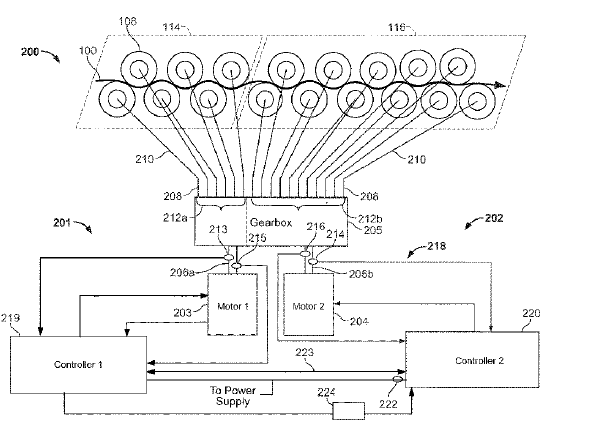
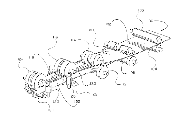
US11045850 — APPARATUS AND METHODS TO INCREASE THE EFFICIENCY OF ROLL-FORMING AND LEVELING SYSTEMS — The Bradbury Company, Inc. (USA) — Methods and apparatus to increase the efficiency of roll-forming and leveling systems are described herein. An example strip material processing apparatus includes a first drive system to drive an exit work roll at an exit of the strip material processing apparatus, and a second drive system to drive an entry work roll at an entry of the strip material processing apparatus, where the strip material is to travel through the strip material processing apparatus from the entry to the exit. The example strip material processing apparatus also includes a controller to provide a first command reference to the first drive system to drive the exit work roll at the first command reference. The controller is to determine a first torque value of the first drive system when the first drive system operates at the first command reference, and the controller is to determine a second torque value based on a ratio of the first torque value to the second torque value such that the first torque value and the second torque value are different. The controller is to also drive the entry work roll via the second drive system to maintain the ratio.
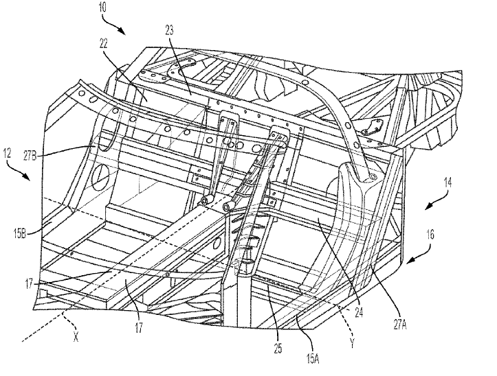
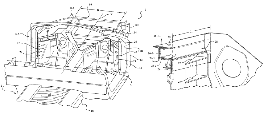
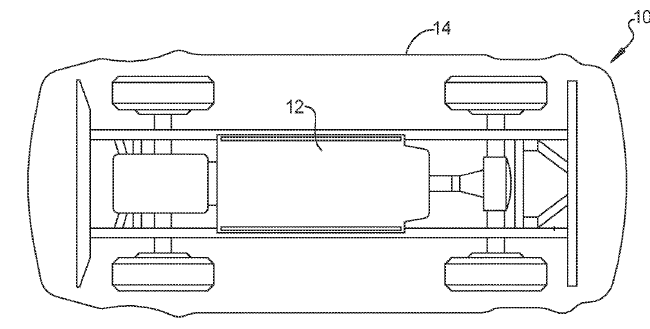
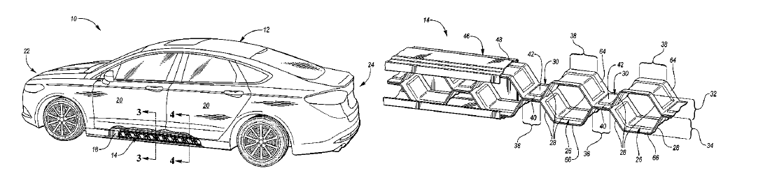
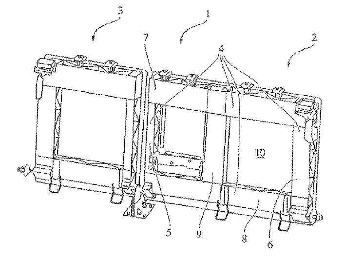
US11001304 — VEHICLE STRUCTURE FOR SIDE IMPACT LOAD PATH MANAGEMENT — GM Global Technology Operations LLC (USA) — A side impact load management system for a vehicle having a vehicle frame includes a plurality of cross-vehicle support members made of high strength aluminum tubular extrusions, generally tubular with a three-cell structure, extending from a first side of the vehicle to a second side of the vehicle. A first structural member extends in a first vertical plane parallel to a vehicle body axis defined by the vehicle frame and coupled to the vehicle frame, the first structural member connecting the plurality of cross-vehicle support members on the first side of the vehicle. A second structural member extends in a second vertical plane parallel to the vehicle body axis defined by the vehicle frame and coupled to the vehicle frame, the second structural member connecting the plurality of cross-vehicle support members on the second side of the vehicle. The first and second structural members are configured to transfer a side impact load simultaneously to the plurality of cross-vehicle support members. he first and second side frame rails, which may be formed from aluminum by appropriate processes including roll forming are arranged substantially symmetrically with respect to the longitudinal vehicle centerline or the X-axis.
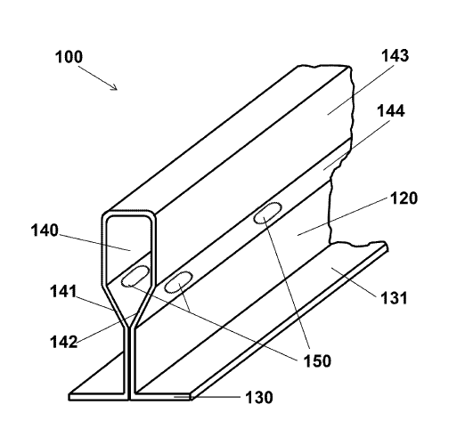
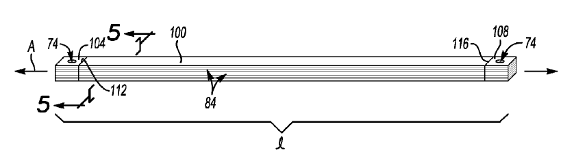
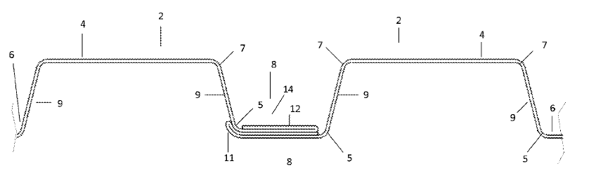
US10995490 — SUPPORT MEMBER FOR CEILING SYSTEM — CertainTeed Ceilings Corporation (USA) — The disclosure relates to roll formed support members made of aluminum for ceiling systems, such as those that can be formed into an interconnected grid to be suspended from a ceiling and support ceiling tiles. One aspect of the disclosure is a linearly-extending support member for a ceiling tile. The support member has a cross-sectional shape that includes a substantially vertical central web with a top end and a bottom end; at least one flange extending substantially horizontally from the bottom end of the web, the flange having an upper surface and a lower surface; and a bulb extending from the top end of the web, the bulb having a first side and a second side with a cavity therebetween, the bulb having an upper portion and a lower portion adjacent the top end of the web, wherein the entire lower portion of the bulb is narrower than the upper portion of the bulb and wider than the central web, the bulb comprising a series of spaced apertures formed therein through both the first side and the second side of the bulb, each aperture being disposed at least partially in the lower portion of the bulb, each aperture having an upper portion and a lower portion, wherein the upper portion of the aperture is rounded.
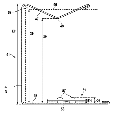
US10961706 — SYSTEM, METHOD AND APPARATUS FOR WALL SUPPORT OF CEILING SUSPENSION GRID — CertainTeed Ceilings Corporation (USA) — A ceiling suspension system is disclosed and includes a plurality of grid members configured to form a grid for the ceiling suspension system, each grid member comprising a bulb, a web and a flange. The support members may be suitably roll=formed steel or aluminum, extruded aluminum, plastic or fiber-reinforced plastic, depending on the application. The system also includes a plurality of wall support brackets configured to mount the grid to walls in a structure. Each wall support bracket comprises a vertical back, a lower flange at a lower end of the vertical back, and an upper flange at an upper end of the vertical back. Further, the upper flange is generally V-shaped when viewed longitudinally and each wall support bracket only one tab in the lower flange for each grid member. Moreover, the only one tab is configured to engage and retain the flange of a respective grid member, such that the respective grid member rests on the lower flange.
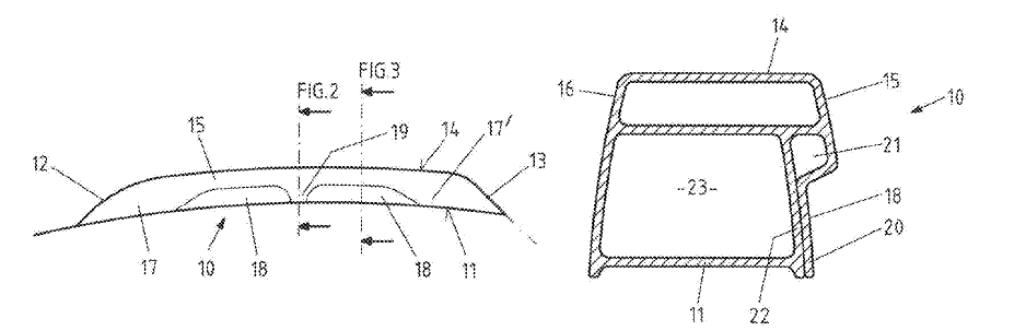
US10953806 — ROOF RACK FOR A MOTOR VEHICLE — WKW Engineering GmbH (Germany) — The invention relates to a roof rack roof rack for a motor vehicle, having a roof rail profile. The roof rail profile is manufactured from a profile that has a constant cross-section in the longitudinal direction of the profile. Roof rail profiles with different designs can be formed from one and the same profile cross-section, namely by the shaping of a side or wall section present on the profile that delimits a passage. The roof rail profile, which preferably is designed as one piece, has different cross-sections in the longitudinal direction, namely unshaped surface sections and shaped surface sections. A profile of this nature can be manufactured by roll-forming or extrusion from aluminum or an aluminum alloy, preferably by roll-forming.
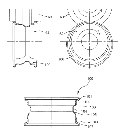
US10946428 — SPINNING APPARATUS AND SPINNING METHOD — Topy Kogyo Kabushiki Kaisha (Japan) — A spinning apparatus for the production of a vehicle wheel rim involves decreasing by spinning a thickness of a portion of a tube material having a uniform thickness except at a first axial end portion is disclosed. he tube material is made from metal, and the metal is, for example, steel. Alternatively, the tube material may be made from non-ferrous metal (including aluminum, magnesium, titanium, and alloys thereof). The spinning apparatus includes a spindle-side chuck having a conical concavity and a mandrel. The mandrel has a mandrel-side chuck formed in a form of a conical convexity corresponding in configuration to the conical concavity of the spindle-side chuck and a cylindrical portion for supporting the tube material. The spinning apparatus further includes a spinning roll for decreasing the thickness of the tube material by pressing the spinning roll against the tube material when the tube material is supported by the cylindrical portion of the mandrel. A roll-forming step is conducted after axially opposite ends of the formed tube have been flared, In the roll-forming, a wall of the formed tube is squeezed between a lower roll and an upper roll and then the rolls are rotated, thereby forming the formed tube to a configuration of the vehicle wheel rim.
US10940893 — REINFORCED OPEN-SECTION STRUCTURAL PANEL — GM Global Technology Operations LLC (USA) — A bulkhead for a vehicle body structure includes a panel. The panel has a contour defined by a contour length and characterized by an open section having three surfaces in a cross-sectional view. The bulkhead also includes a n aluminum alloy support member having a yield strength of at least 220 MPa embedded in the panel. The support member includes an external form configured to interface with and match at least two of the three surfaces of the contour. The support member also includes a support member length configured to fit within the contour length and a boxed cross-section having a substantially uniform shape along the support member length. The bulkhead additionally includes an adhesive applied between the external form of the support member and the interfacing surfaces of the contour to thereby bond the support member to the panel and reinforce the bulkhead. A vehicle having a structure with such a bulkhead is also considered. A bulkhead for a vehicle body structure includes a panel. The panel has a contour defined by a contour length and characterized by an open section having three surfaces in a cross-sectional view. The bulkhead also includes a support member embedded in the panel. Two frame rails in the body structure may be constructed from aluminum, and be formed by one or more appropriate methods, such as extrusion, hydro-forming, roll-forming, stamping, and welding.
US10933455 — TUBULAR CORE AND METHOD — Pacific Roller Die Company, Inc. (USA) — Disclosed is a tubular core on which sheets of metal or other material can be wound and supported, for shipment, handling and dispersal, and a method for forming the core. The core comprises a metal sheet or strip which has a rectangular-ribbed cross-sectional profile comprising rectangular, flat ribs, and which is wound spirally into a tubular configuration. The core is formed by passing the strip through a plurality of roll-forming stands, to progressively form sections of the ribs and progressively define the sections into the rectangular ribbed profile in which the flat ribs collectively form a support surface for the sheets which are to be wound on the core. The method applies to aluminum strip that is 0.005” to 0.050” thick.
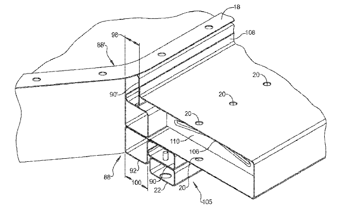
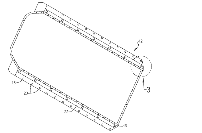
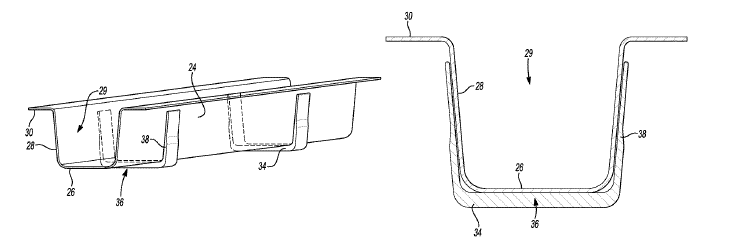
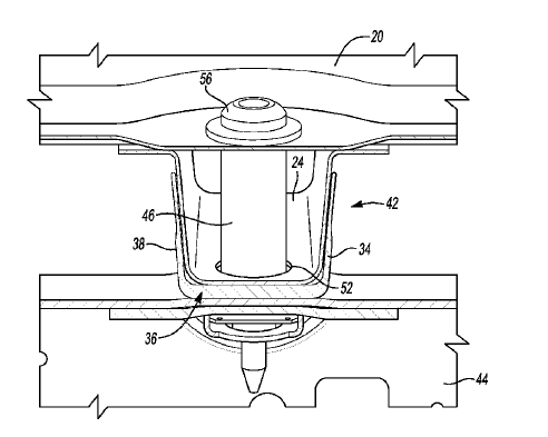
US10894469 — AUTOMOBILE VEHICLE BATTERY TRAY WITH ROLL-FORMED MEMBERS — Dura Operating, LLC (USA) — A battery tray for a battery powered vehicle includes a battery tray having a side wall. An impact absorbing structure is connected to the side wall. The impact absorbing structure includes at least one roll-formed member fixed to the side wall. The at least one roll-formed member is created from a single metal plate and includes a first plate portion roll-formed to create a first cavity and having a first flange created in a member central wall of the first plate portion. The first flange is fixed to the first plate portion. A second plate portion is roll-formed to create a second cavity and has a second flange at an end of the second plate portion fixed to the member central wall. A roll-formed U-shaped attachment member is fixed to the at least one roll-formed member. A battery tray having impact absorbing structures and roll-formed members of the present disclosure offers several advantages. These include the incorporation of roll-formed members which are inexpensive to produce, use spot-welding fixed connections where possible, and absorb impact energy in an efficient space envelope.
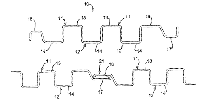
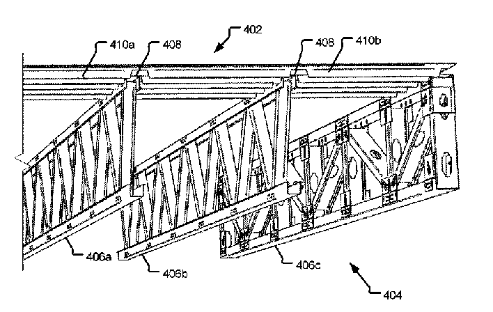
US10870986 — METAL DECKING — PatCo, LLC (USA) — In one implementation, a metal deck is provided that includes a plurality of deck components formed in a contiguous metal sheet. Each of the deck components includes a plurality of folded ribs formed along the length of the metal deck. Each of the plurality of folded ribs are configured such that one or more trusses of a building may fit between the plurality of folded ribs. The metal deck may be used to complete the structural diaphragm without using concrete. As an example, the metal deck includes a plurality of deck components and may be formed as one contiguous manufactured product having the deck components joined to each other. For example, the metal deck may be formed from a metal sheet using a roll-forming machine. The thickness of the sheet used to form the metal deck may be, for example, 16-18 gauge (between 0.0625 to 0.0500 inches) for stainless steel sheets. However, alternate thickness of the metal sheet may also be used. Similarly, alternative materials used in building construction, such as galvanized steel, aluminum, etc., may also be used.
US10800245 — AUTOMOBILE VEHICLE BATTERY TRAY WITH LOWER IMPACT RAILS — Dura Operating, LLC (USA) — A battery tray assembly for a battery powered vehicle includes a tub having a bottom wall connected with a side wall. A side rail assembly is connected to the side wall of the tub. A lower impact rail is connected to the side rail assembly. The lower impact rail extends beyond the bottom wall of the tub. The lower impact rail is removably connected to the side rail assembly by a fastener. The collapsible frame can be made for example by roll forming one or more materials such as rolled metal plate including steel or aluminum.
US10773582 — AUTOMOBILE VEHICLE BATTERY TRAY WITH SIDE IMPACT RAILS — Dura Operating, LLC (USA) — A battery tray for a battery powered vehicle includes a battery tray having a side wall. An impact absorbing structure is connected to the side wall. The impact absorbing structure includes at least one roll-formed member fixed to the side wall. The at least one roll-formed member is created from a single metal plate and includes a first plate portion roll-formed to create a first cavity and having a first flange created in a member central wall of the first plate portion. The first flange is fixed to the first plate portion. A second plate portion is roll-formed to create a second cavity and has a second flange at an end of the second plate portion fixed to the member central wall. A roll-formed U-shaped attachment member is fixed to the at least one roll-formed member. Each side wall impact absorbing structure includes a first B-shaped roll formed member fixed to a side wall of the battery tray and a second B-shaped roll-formed member oriented substantially perpendicular to the first B-shaped roll-formed member. The first B-shaped roll-formed member, the second B-shaped roll-formed member, the stiffening plates and the U-shaped attachment member are fixed together for example by welding, for example by MIG or laser welding, and collectively create an impact absorbing structure. The impact absorbing structure is also attached to the tub, preferably be welding, such as MIG or laser welding. The collapsible frame can be made for example from one or more materials such as rolled metal plate including steel or aluminum.
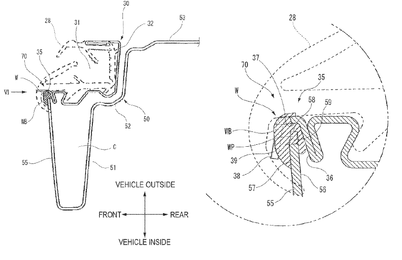
US10549609 — DOOR FRAME — Shiroki Corporation (Japan) — A vehicle door frame includes: an outer joint part of an outer member and an inner joint part of an inner member are welded at a plurality of welding portion; wherein, in a cross-section orthogonal to an longitudinal direction, the inner joint part includes an inner inside surface an inner outside surface and an inner side surface, and the outer joint part includes an outer inside surface and an outer side surface; wherein, in at least one of the welding portions, an inner notch is provided at an outer edge of the inner joint part and a weld path is formed between the inner side surface and the outer side surface; and wherein a weld bead, which is formed to fill the weld path, is attached to the inner outside surface, the inner side surface, the inner inside surface, the outer side surface, and the outer inside surface. The outer member is formed in the shape of a long member by roll-forming, for example, a planar metal material, steel or aluminum, and the inner member is formed in the shape of a long member by press-forming a planar metal material such as steek or aluminum, similar to the outer member. The inner member is integrally formed in the outer member by welding in a plurality of welding portions with intervals in a longitudinal direction.
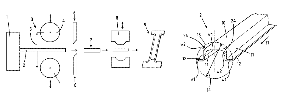
US10486221 — METHOD FOR PRODUCING A MOTOR VEHICLE COMPONENT — Benteler Automobiltechnik GmbH (Germany) — A method for producing a motor vehicle component, e.g., a pillar having an upper roof connection region and a lower sill connection region, from a lightweight metal alloy, such as a 5xxx, 6xxx, or 7xxx aluminum alloy, is disclosed including extruding a profile having at least two wall thicknesses that are mutually dissimilar in the cross section, rolling the extruded profile in portions in the extrusion direction. The rollers in the roller spacing thereof are variable. Cutting-to-length the extruded and in portions rolled profile to form a semi-finished product and forming the semi-finished product to form the motor vehicle component. The method further widens a portion of the cross section of the profile in a longitudinal direction by the rolling, which is performed directly after profile extrusion having residual heat at a temperature of 350-550°C or performing the rolling or the forming upon cooling of the semi-finished product at 20-100°C.
US10465384 — STRUCTURAL DECKING SYSTEM — Nucor Corporation (USA) — Embodiments of the invention include structural decking systems with at least a four-layered seam and methods for manufacturing and assembling structural decking systems with at least four-layered seams. The decking panels may be provided with an edge having an exposed “male lip” with two layers, and an opposite edge having a “female lip” with two layers. Individual panels may be coupled together by placing the female lip of a first panel over the male lip of an adjacent panel, thus creating an un-joined seam. To couple the panels together, the panels may be secured through various couplings configurations. The couplings may be formed by deforming, cutting, and/or welding the seam. Not only do the couplings help prevent vertical separation between adjacent panels, but the couplings minimize lateral shifting along the seam, and ensure a desired level of shear strength in the seam and across the structural decking system. The decking panels used to roll form the structural decking may be made from steel or aluminum or other rigid material, although typical panels are made of steel sized 12-42 inches wide by 1-50 feet long and have a thickness that depends on engineering specification.
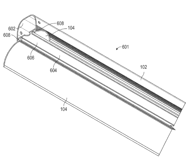
US10415800 — LIGHT FIXTURES WITH INTEGRATED FEATURES — ABL IP Holding LLC (USA) — A light fixture includes a housing, an optic, and a wing. The housing is configured to house at least one light source of the light fixture. The wing extends from the side of the housing. In some embodiments, the housing and wing are monolithically formed as an integral unit. In other embodiments, the optic and wing are monolithically formed as an integral unit. According to further embodiments, the housing, optic, and wing are monolithically formed as an integral unit. The housing can be of any shape and dimension. In some embodiments, the housing is formed from a material having suitable thermal management capabilities to conduct heat generated by the light fixture during use. Various materials having suitable thermal management capabilities for the housing include aluminum. The housing may be formed using a variety of different technologies or processes, including, but not limited to, extrusion, roll-forming, die-forming, stamping, casting, etc.
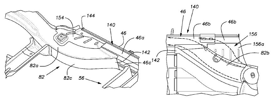
US10370040 — VEHICLE IMPACT ABSORBING STRUCTURE — Ford Global Technologies, LLC (USA) — A vehicle body includes a floor side panel, a rocker panel, and a reinforcement structure. The floor side panel is secured to the rocker panel. The floor side panel and the rocker panel each extend longitudinally from a front to a rear of the vehicle body and define a cavity therebetween. The reinforcement structure is disposed within the cavity and forms a plurality of longitudinally aligned crush cans. Each crush can is aligned laterally from the floor side panel to the rocker panel. The upper panel and the lower panel may be made via stamping, roll-forming, casting, hydroforming, or any other manufacturing process. In at least one approach, the upper panel, lower panel, and the external case may each be made from a rolled sheet metal material such as rolled steel or rolled aluminum. The crush cans formed by the lower panel and upper are oriented to face laterally outward from the vehicle or vehicle body to absorb or transfer energy during side impacts or collisions. The exterior walls of the external case 46 are oriented to extend longitudinally from the front to the rear of the vehicle to absorb or transfer energy during front and rear impacts or collisions, which may be head-on, oblique, or offset impacts or collisions.
US10252306 — APPARATUS AND METHODS TO INCREASE THE EFFICIENCY OF ROLL-FORMING AND LEVELING SYSTEMS — The Bradbury Company, Inc. (USA) — Methods and apparatus to increase the efficiency of roll-forming and leveling systems are described herein. An example strip material processing apparatus includes a first drive system to drive an exit work roll at an exit of the strip material processing apparatus, and a second drive system to drive an entry work roll at an entry of the strip material processing apparatus, where the strip material is to travel through the strip material processing apparatus from the entry to the exit. The example strip material processing apparatus also includes a controller to provide a first command reference to the first drive system to drive the exit work roll at the first command reference. The controller is to determine a first torque value of the first drive system when the first drive system operates at the first command reference, and the controller is to determine a second torque value based on a ratio of the first torque value to the second torque value such that the first torque value and the second torque value are different. The controller is to also drive the entry work roll via the second drive system to maintain the ratio.
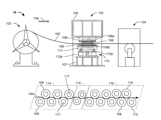
US10243191 — FLEXIBLE MULTI-LAYERED BUS BAR — Ford Global Technologies, LLC (USA) — A battery pack of an electrified vehicle can include a plurality of battery cell assemblies arranged in one or more battery arrays. Bus bars can be used to distribute power to and from the battery cell assemblies, and to and from the battery pack. Bus bars are typically copper and can add significant weight to the electrified vehicle. An exemplary bus bar assembly includes a roll bonded first layer and a second layer directly adjacent the first layer. The first layer and the second layer each have a section made of a first material and extending from a first end portion to an opposing, second end portion. The first and second end portions include a second material different than the first material. In a non-limiting embodiment of any of the foregoing bus bar assemblies, the first material comprises aluminum and the second material comprises copper, each roll bonded to the other. In one embodiment, the bi-metallic interface after roll forming includes a rectangular protrusion. In another embodiment, a bimetallic interface after roll forming includes an angled edge of a strip.
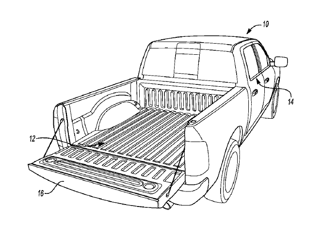
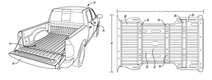
US10226799 — CARGO BED SUPPORT ASSEMBLY FOR A TRUCK — Ford Global Technologies, LLC (USA) — A method of manufacturing a reinforcement assembly for a truck bed is provided. The method includes roll-forming an aluminum sheet to form a cross-member having a base, a pair of opposing sidewalls extending from the base, and a pair of flanges each extending from one of the sidewalls and substantially parallel with the base. The method includes extruding an aluminum reinforcement member and attaching the reinforcement member to the cross-member to space the cross-member from a frame rail of the truck. According to one embodiment, a vehicle comprises a 6000-series aluminum truck bed having a width, a top surface. and a bottom surface. A 6000-series aluminum cross-member is mounted to the bottom surface of the truck bed and extends along the width of the truck bed. The vehicle may also include a “U”-shaped extruded 6000-series aluminum reinforcement member attached to an underside of the cross member, wherein the reinforcement member includes a base secured between a frame rail and the cross-member. The cross-member may also have sidewalls extending from a base to define a channel, and flanges extending from the sidewalls away from the channel. The reinforcement member can be positioned outside of the channel with its sidewalls and base contacting the respective sidewalls and base of the cross-member.
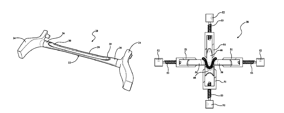
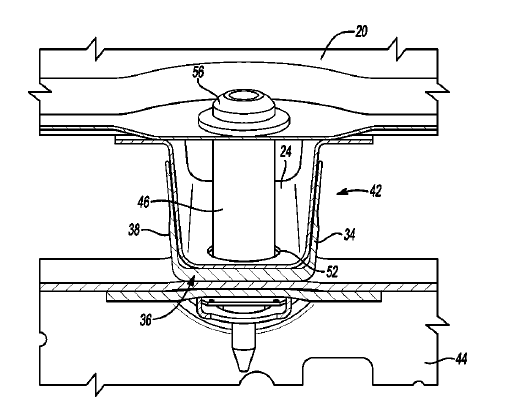
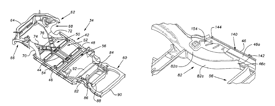
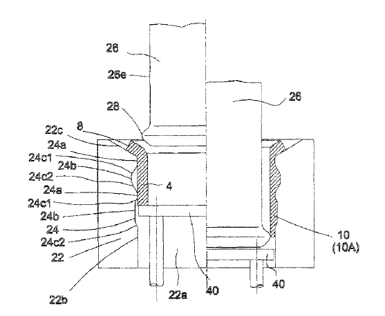
US10137952 — METHOD OF MANUFACTURING SUPPORT STRUCTURE FOR A PICKUP TRUCK BED — Ford Global Technologies, LLC (USA) — A vehicle includes a pair of longitudinal frame rails and a bed above the frame rails. A plurality of roll-formed aluminum cross-members contact the bed and are disposed between the bed and the frame rails for additional support of the bed. Extruded aluminum spacers are disposed between and in contact with the one of the cross members and one of the frame rails. A crush tube is spin-welded to the spacer and contacts the underside of the bed for additional support to inhibit downward relative movement of the bed. The crush tube is formed with a longitudinal hole extending to receive a fastener that extends from above the truck bed, through the crush tube hole, through the cross-member and spacer, and into the frame rail.
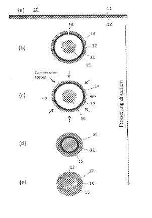
US10077493 — METHODS FOR APPLYING ALUMINUM COATING LAYER TO A CORE OF COPPER WIRE — AFL Telecommunications LLC (USA) — Methods of applying aluminum coating layers over copper wires are disclosed. A first method may include applying aluminum powder to the surface of a rod, passing the rod through a first set of compression rolls thereby forcing the aluminum powder into a compacted preform around the rod, and heating the rod covered by the preform at 550oC. to 620oC. Further, the heated preform coated rod is passed through a second set of compression rolls thereby obtaining an aluminum coated copper rod. A second method includes disposing a copper rod inside an aluminum tube roll, formed from aluminum strip such as AA3003 or AA1100 or similar, with a thickness between 0.50 to 1.0 mm and may have a brazing alloy such as AA4104 or similar on one side. The roll formed aluminum tube is formed so that the brazing alloy is on the inside of the roll formed tube whereby the seam is welded under inert gas. The diameter of the tube inner surface is reduced to match the copper rod, and the composite tube-rod is heated such that the inner layer fuses to the rod.
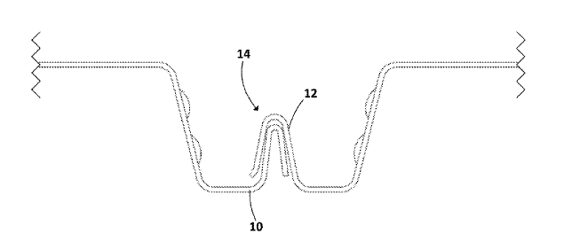
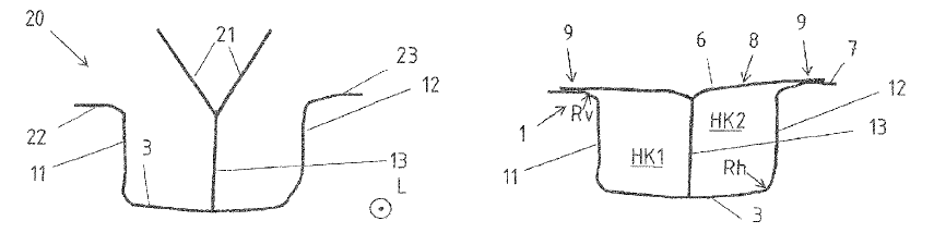
US9975506 — IMPACT BEAM FOR A MOTOR VEHICLE AND METHOD FOR PRODUCTION THEREOF — Benteler Automobiltechnik GmbH (Germany) — An impact beam made of a high strength aluminum alloy for a motor vehicle, said impact beam includes a front wall, a rear wall and at least two transverse walls connecting the front wall and the rear wall. The front wall has a single-layered section and a multilayered section, wherein the multilayered section is formed by a first and a second front wall section, wherein the first front wall section is fixedly connected with the second front wall section, wherein at least the single-layered front wall section, the rear wall and the at least two transverse walls together enclose a hollow chamber. The front wall, the rear wall and the transverse walls are configured in one-piece and of a same material, wherein the impact beam is made of a longitudinal starting section with a constant U-shaped cross section with transverse walls that can be folded over into a hollow section by means of multiple roller sets that are arranged in longitudinal direction of the extruded section or the starting section.
US9863146 — STRUCTURAL PANEL SYSTEMS WITH A NESTED SIDELAP AND METHOD OF SECURING — Nucor Corporation (USA) — The invention relates to structural panel systems with at least a four-layered generally in-plane sidelap, at least a three layer generally in-plane sidelap, or corner sidelaps of various layers, and methods for manufacturing and assembling structural panel systems with these types of sidelaps. The structural panels may be provided with an edge having a “lower lip” with two layers, and an opposite edge having an “upper lip” with two layers. Individual panels may be coupled together by placing the upper lip of a first panel over the lower lip of an adjacent panel, thus creating an un-joined sidelap. The lips may have nested portions for helping to place one lip over the other. The panels may be operatively coupled through various couplings configurations, such as fasteners, welding, cutting the sidelap, or the like. The present invention improves the shear strength of the structural panel system and reduces costs. The upper and lower lip may be manufactured by a roll forming process that shapes sheets of metal into desired shapes through one or more rolling stages using one or more rollers.
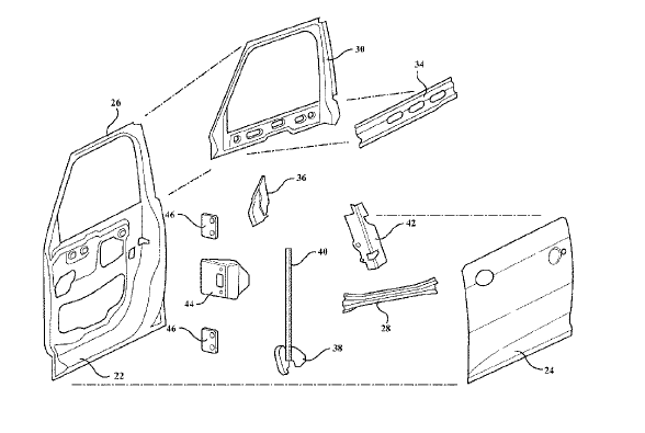
US9834070 — VEHICLE DOOR — Magna International Inc. (Canada) — A door assembly for a vehicle is provided. The door assembly includes an inner panel and an outer panel which are joined together to define a central space therebetween. The central space has a front which faces towards the front of a vehicle and a back which faces towards a back of the vehicle. Both the inner and outer panels are made of aluminum, and at least one reinforcement beam made of steel is disposed in the central space between the aluminum inner and outer panels to provide the door assembly with increased impact resistance. The aluminum inner and outer panels may be formed through any suitable process including, for example, stamping, roll-forming, extrusion, and casting. The method proceeds with the step of joining the aluminum panels together such that a central space is defined between the panels and wherein the central space has a front and a back. The method continues with the step of joining at least one reinforcement beam made of steel to at least one of the aluminum inner and outer panels in the central space such that the at least one reinforcement beam extends lengthwise between the front and back of the central space for increasing the impact resistance of the door assembly.
US9783865 — THERMAL-ASSISTED ROLL FORMING OF HIGH STRENGTH MATERIAL — GM Global Technology Operations LLC (USA) — A thermal-assisted method deforms plastically a high-strength material using a high-intensive heat source. The high-strength material may be a cold-rolled sheet aluminum of strength greater than 300 megapascal (MPa) or a cold-rolled sheet steel of strength greater than 1000 MPa. The cold-rolled sheet metal is heated just before bending to a temperature near or above the critical temperature for the material or the material and is followed by rapid quenching after bending. The process comprises continuously feeding high-strength cold rolled sheet metal between rollers on a roll-forming production line, providing intense local heat from a heat source that is targeted at the location that will subsequently become bent upon entering the rollers, heating the cold rolled sheet metal to a temperature within the two-phase sub-critical temperature region or above the critical temperature for producing the high temperature phase, bending the cold rolled sheet metal, and rapidly quenching the cold rolled sheet metal after bending. The rapid quench allows the alloys that demonstrate subsequent precipitation hardening, such as aluminum or magnesium, to retain the high temperature phase structure at room temperature.
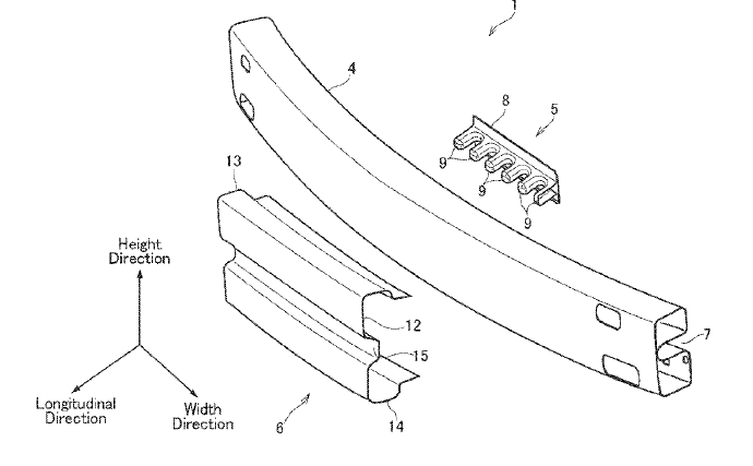
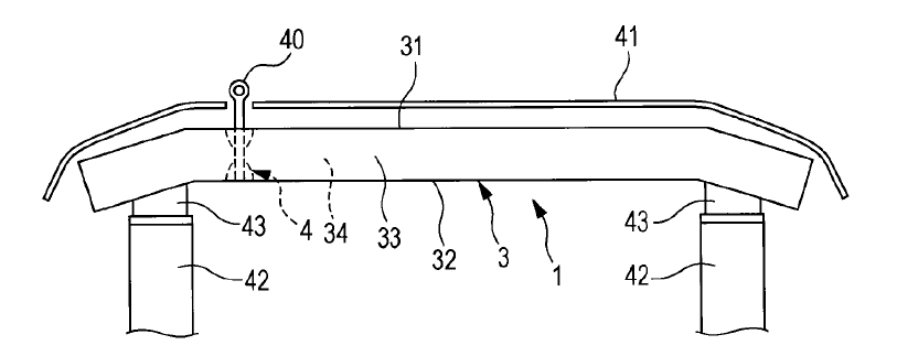
US9751479 — VEHICLE BUMPER REINFORCEMENT STRUCTURE — Toyota Jidosha Kabushiki Kaisha (Japan) — A vehicle bumper reinforcement structure to increase energy absorption capacity is provided. The vehicle bumper reinforcement structure comprises a base member extending in the width direction of the vehicle that is attached to the vehicle at both width ends, and a first reinforcement member and a second reinforcement member attached to the base member at a width center of the vehicle. Widths of the reinforcement members are differentiated in such a manner to cause fracture of the base member at width ends of the reinforcement members by a predetermined collision impact applied to the width center of the base member. The base member is formed by a roll forming method using metal sheet having a constant thickness and is shaped into a hollow rectangular structure.
US9527120 — TRANSVERSE STRUT AND METHOD OF FORMING A TRANSVERSE STRUT — Magna International Inc. (Canada) — A roll forming assembly for forming a transverse strut from a tube is provided. The roll forming assembly includes a heater, such as an induction heater, for heating a tube to a predetermined annealing temperature. Next, the tube is fed to a roll former, which includes a plurality of forming wheels to shape the tube into a transverse strut. Servo motors are operably coupled to the forming wheels for adjusting the positions of the forming wheels in a radial direction during the roll forming process to give the transverse strut a variable profile along its length. After the roll forming process is completed, the transverse strut is quenched so that its base material is given a predetermined microstructure. The tube is preferably of one or more metals, such as various grades or alloys of steel, aluminum, iron, magnesium, etc. However, it should be appreciated that the tube could be of any desirable type of formable material.
US9487246 — CARGO BED SUPPORT ASSEMBLY FOR A TRUCK — Ford Global Technologies, LLC (USA) — A cargo bed assembly for a pickup truck includes an aluminum truck bed above a pair of frame rails. A plurality of roll-formed 6000-series aluminum cross-members extend along a width of the truck bed and contact the underside of the truck bed. The cross-members include longitudinal channels. Each cross-member contacts a pair of extruded 6000-series aluminum spacers underneath the cross-member at spaced locations to align with the frame rails. The spacers contact the frame rails and at least partially surround a portion of the outer surface of the cross-members to separate the cross-members from the frame rails. In an embodiment, a method of manufacturing a reinforcement assembly for a truck bed includes roll forming an aluminum sheet to form a cross-member having a base, a pair of opposing side walls extending from the base, and a pair of flanges each extending from one of the sidewalls and substantially parallel with the base. Aluminum is extruded to provide an extruded aluminum reinforcement member. The method then includes attaching the reinforcement member to the cross-member to space the cross-member from a frame rail of the truck.
US9422010 — VEHICLE BED FRAME ASSEMBLY, SYSTEM AND METHOD — Honda Motor Co., Ltd. (Japan) — A vehicle frame assembly, system and method includes a vehicle frame assembly having a variable length longitudinal frame component. The longitudinal frame component is roll formed at a first length when used on a first vehicle type and formed at a second length when used on a second vehicle type. In one example, the longitudinal frame components are roll-formed components formed by a roll-form process and cut to a desired length (e.g., a first longitudinal length for the first vehicle type and a second longitudinal length for the second vehicle type). Roll-forming could be the process used when the longitudinal components are formed of steel, for example, though this is not required. In another example, the longitudinal components are extruded components formed by an extrusion process and cut to a desired length (e.g., a first longitudinal length for the first vehicle type and a second longitudinal length for the second vehicle type). Extrusion could be the process used when the longitudinal components are formed of aluminum, for example, though this is not required. In still another example, some other process could be used to form the variable length longitudinal components, including but not limited to press braking, stamping, etc.
US9365085 — BUMPER REINFORCEMENT AND METHOD OF MANUFACTURING THE SAME — Kobe Steel, Ltd. (Japan) — A bumper reinforcement includes a tubular body including a front wall that serves as an impact surface and a rear wall on a vehicle body side, the tubular body, made of a roll formed steel or aluminum alloy sheet or an extrusion, extending in a vehicle width direction and having a hollow cross section; and a tow hook attachment structure for allowing a tow hook to be removably attached thereto. The tow hook attachment structure includes a pair of cylindrical protrusions, formed by press forming or roll forming, respectively integrally formed with the front and rear walls of the tubular body by shaping parts of the walls, the cylindrical protrusions being disposed at predetermined positions on the front and rear walls in the vehicle width direction so as to face each other and so as to protrude inward into the hollow cross section, and at least one of the pair of protrusions includes a threaded portion for allowing a threaded portion of the tow hook to be screwed thereinto.
US9254769 — STRUCTURAL ELEMENT FOR A MOTOR VEHICLE — Johnson Controls GmbH (Germany) — The invention relates to a structural element (100) of a motor vehicle seat, wherein the structural element (100) comprises a first component (101) and a second component (102). In an overlap region (103), the first component (101) and the second component (102) have a formed-closed connection, or a form-closed and form-closed connection, wherein the connection in the overlap region (103) can be produced by an electromagnetic pulse shaping method. The first component 101 preferably comprises a high-strength material, for example a steel material or a fiber-reinforced plastics material. The second component 102 comprises an electrically conductive material, and, preferably, use is made of a light metal, such as aluminum or magnesium, and alloyed steel or a material consisting of material-to-material bonding connections of different materials. To connect the first component to the second component, the components are connected to each other in an interlocking or interlocking and frictional manner in the overlapping regions 103, 103′ by means of an electromagnetic pulse shaping method. The use of hybrid structures consisting of sheet-metal and aluminum profiles enables a substantial reduction in weight. In addition to the methods already mentioned, use may be made alternatively or in combination of cohesive bonding, interlocking and/or frictional connecting techniques, for example welding (for example MIG), CMT welding (cold metal transfer–in the case of aluminum-steel combinations), plug-in/screw connections, junction element connections, rivet connections, press-joining, cold roll-forming, or press connections.
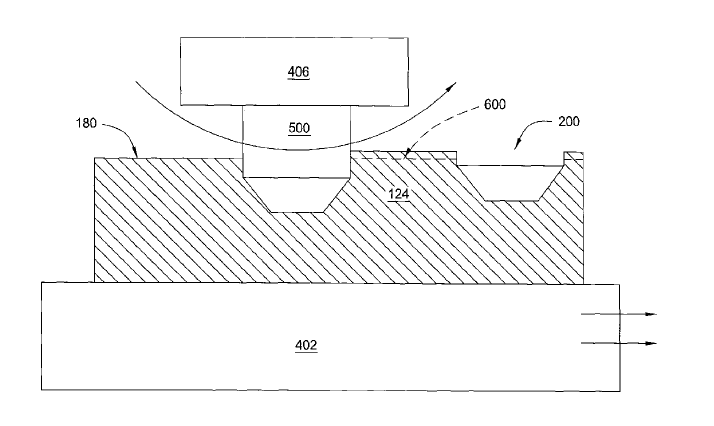
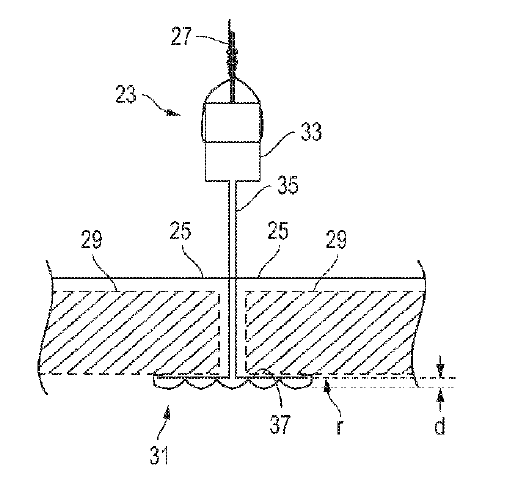
US9243328 — SUSCEPTOR WITH ROLL-FORMED SURFACE AND METHOD FOR MAKING SAME — Applied Materials, Inc. (USA) — The present invention generally provides apparatus for supporting a large area substrate in a plasma reactor. More particularly, embodiments of the present invention relate to a substrate support for supporting large area substrates in semiconductor processing and a method of fabricating the same. One embodiment, a substrate support for use in a plasma reactor includes an electrically conductive body that has a top surface with a plurality of roll-formed indents. A plasma reactor is also provided. In another embodiment, a plasma reactor includes a chamber body having a process volume. A showerhead is disposed in the process volume and configured to direct flow of provide process gases into the process volume. An aluminum body is disposed in the process volume below the showerhead. A heater is disposed in the aluminum body which has a top surface containing roll-formed indents.
US9221500 — CRUSH TUBE AND SUPPORT STRUCTURE FOR A PICKUP TRUCK BED — Ford Global Technologies, LLC (USA) — A vehicle includes a pair of longitudinal frame rails and a bed above the frame rails. A plurality of roll-formed aluminum cross-members contact the bed and are disposed between the bed and the frame rails for additional support of the bed. The cross-members can be made of 6000-series aluminum that is roll-formed. To supplement the strength of a single-piece roll-formed cross-member, the reinforcement member can be made of extruded 6000-series aluminum that is extruded. Roll-forming is an efficient method of manufacturing a stamped component in which the shape of the component is constant and free of any undulations or stark changes in geometry. A roll-formed cross-member provides a longitudinal, one-piece supporting beam that adequately provides support to the truck bed and extruded aluminum spacers are disposed between and in contact with the one of the cross members and one of the frame rails. A crush tube is spin-welded to the spacer and contacts the underside of the bed for additional support to inhibit downward relative movement of the bed. The crush tube is formed with a longitudinal hole extending through it to receive a fastener that extends from above the truck bed, through the crush tube hole, through the cross-member and spacer, and into the frame rail.
US9091050 — SYSTEM, METHOD AND APPARATUS FOR PATTERNED CEILING SUSPENSION — CertainTeed Corporation (USA) — A ceiling suspension system has support members, which may be roll-formed steel or aluminum or extruded aluminum, that are interconnected to support ceiling panels. The ceiling suspension system is suspended from a building. Each of the support members has a lower surface that is patterned and different in textural appearance than other portions of the support members to define patterned lower surfaces. For example, the patterned lower surfaces may have non-smooth textures that are uniform and symmetrical, or non-uniform and irregular. The patterned lower surfaces may have three-dimensional features such as lines, slots, dimples, protrusions, peaks, and valleys and/or cross-hatching, which may be roll-formed on capping on the support members.
US9090293 — CARGO BED SUPPORT ASSEMBLY FOR A TRUCK — Ford Global Technologies, LLC (USA) — A cargo bed assembly for a pickup truck includes an aluminum truck bed above a pair of frame rails. A plurality of roll-formed 6000-series aluminum cross-members extend along a width of the truck bed and contact the underside of the truck bed. The cross-members include longitudinal channels. Each cross-member contacts a pair of extruded 6000-series aluminum spacers underneath the cross-member at spaced locations to align with the frame rails. The spacers contact the frame rails and at least partially surround a portion of the outer surface of the cross-members to separate the cross-members from the frame rails. In one embodiment, a cargo bed assembly for a truck includes a substantially flat aluminum bed, a cross-member, and a 6000-series extruded aluminum reinforcement member. The extruded aluminum reinforcement member is in contact with the base and at least a portion of the sidewalls and is disposed between the cross-member and a frame rail of the truck.
US9085027 — METHOD OF MANUFACTURING A TUBULAR MEMBER — Topy Kogyo Kabushiki Kaisha (Japan) — A method of manufacturing a tubular member having a non-constant thickness by ironing at least a portion of the tubular material. The ironing apparatus can have a punch and a die, and the die can have a convex and concave side surface opposing the punch. The method can include bending an axial end portion of the tubular material to form a bent portion. The tubular material can then axially engage the die at the bent portion, and then the punch can be moved relative to the die to iron at least a portion of the tubular material. The tubular material can be made from metal, and the metal can be, for example, steel, or a non-ferrous metal including, for example, aluminum, magnesium, titanium, and alloys thereof. A method of manufacturing a tubular member comprises manufacturing the tubular material from a flat material having a constant thickness before the ironing. A method of manufacturing a tubular member according further comprises roll-forming the tubular member having a non-constant thickness to form a vehicle wheel rim.
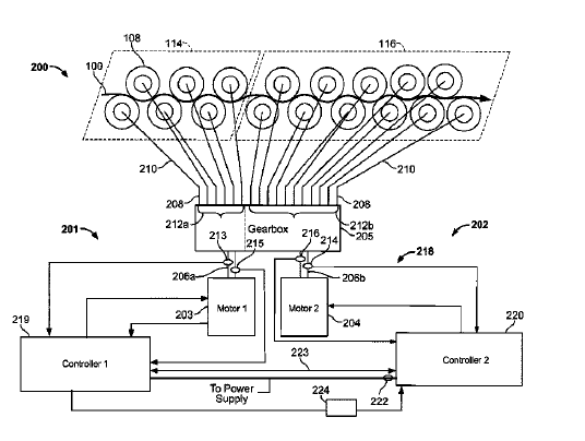
US9050638 — APPARATUS AND METHODS TO INCREASE THE EFFICIENCY OF ROLL-FORMING AND LEVELING SYSTEMS — The Bradbury Company, Inc. (USA) — Methods and Apparatus to increase the efficiency of roll-forming and leveling systems are described herein. An example strip material processing apparatus is described herein includes a first drive system to drive a first plurality of work rolls and a second drive system to drive a second plurality of work rolls. A controller provides a first command reference to the first drive system. The controller measures a first output parameter of the first drive system when the first drive system operates at the first command reference. The controller determines a second command reference based on the first output parameter and the controller drives the second drive system based on the second command reference. The example apparatus, methods and systems described herein employ a torque value or torque vectoring reference (as opposed to a reference speed) to control a multi-drive system. Controlling a multi-drive system with a torque reference as opposed to a speed reference significantly improves the effectiveness of the system by reducing the power consumption of the multi-drive system. When multiple drives are controlled by a torque reference or value, the speeds of the motors of the multi-drive system adjust to meet that torque reference.
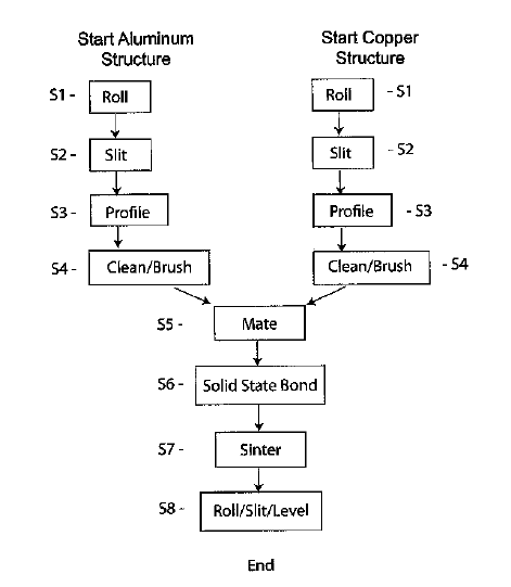
US8999081 — METHODS FOR CREATING SIDE-BY-SIDE METALLIC BONDS BETWEEN DIFFERENT MATERIALS USING SOLID-PHASE BONDING AND THE PRODUCTS PRODUCED THEREBY — Technical Materials Inc. (USA) — Methods of producing composite products for bus bar terminals, battery cells, electrical grounds, and the like formed between at least two different metal structures such as aluminum and copper in a side-by-side configuration are provided. The method includes providing at least two structures made of different materials that are not compatible for welding or conventional cladding processes. A geometric profile is provided for example by roll forming or other method in at least one of the edges of the first structure, and a corresponding mirror image of the geometric profile is provided in a corresponding edge of the second structure. The two structures are positioned together so that the profiled edge or edges form a complimentary composite structure and are then solid-phase bonded to form a composite product. The process may be repeated with additional structure at either end of the first or second structure to achieve multiple side-by-side products. The methods and corresponding products provided herein yield edge to edge products suitable for various electrical connection type applications.
US8960776 — VEHICLE BED FRAME ASSEMBLY, SYSTEM AND METHOD — Honda Motor Co., Ltd. (Japan) — A vehicle frame assembly, system and method includes a vehicle frame assembly having a variable length longitudinal frame component. The longitudinal frame component is formed at a first length when used on a first vehicle type and formed at a second length when used on a second vehicle type. In one example, the longitudinal frame components are roll-formed components formed by a roll-form process and cut to a desired length (e.g., a first longitudinal length for the first vehicle type and a second longitudinal length for the second vehicle type). Roll-forming could be the process used when the longitudinal components are formed of steel, for example, though this is not required. In another example, the longitudinal components are extruded components formed by an extrusion process and cut to a desired length (e.g., a first longitudinal length for the first vehicle type and a second longitudinal length for the second vehicle type). Extrusion could be the process used when the longitudinal components are formed of aluminum, for example, though this is not required. In still another example, some other process could be used to form the variable length longitudinal components, including but not limited to press braking, stamping, etc.