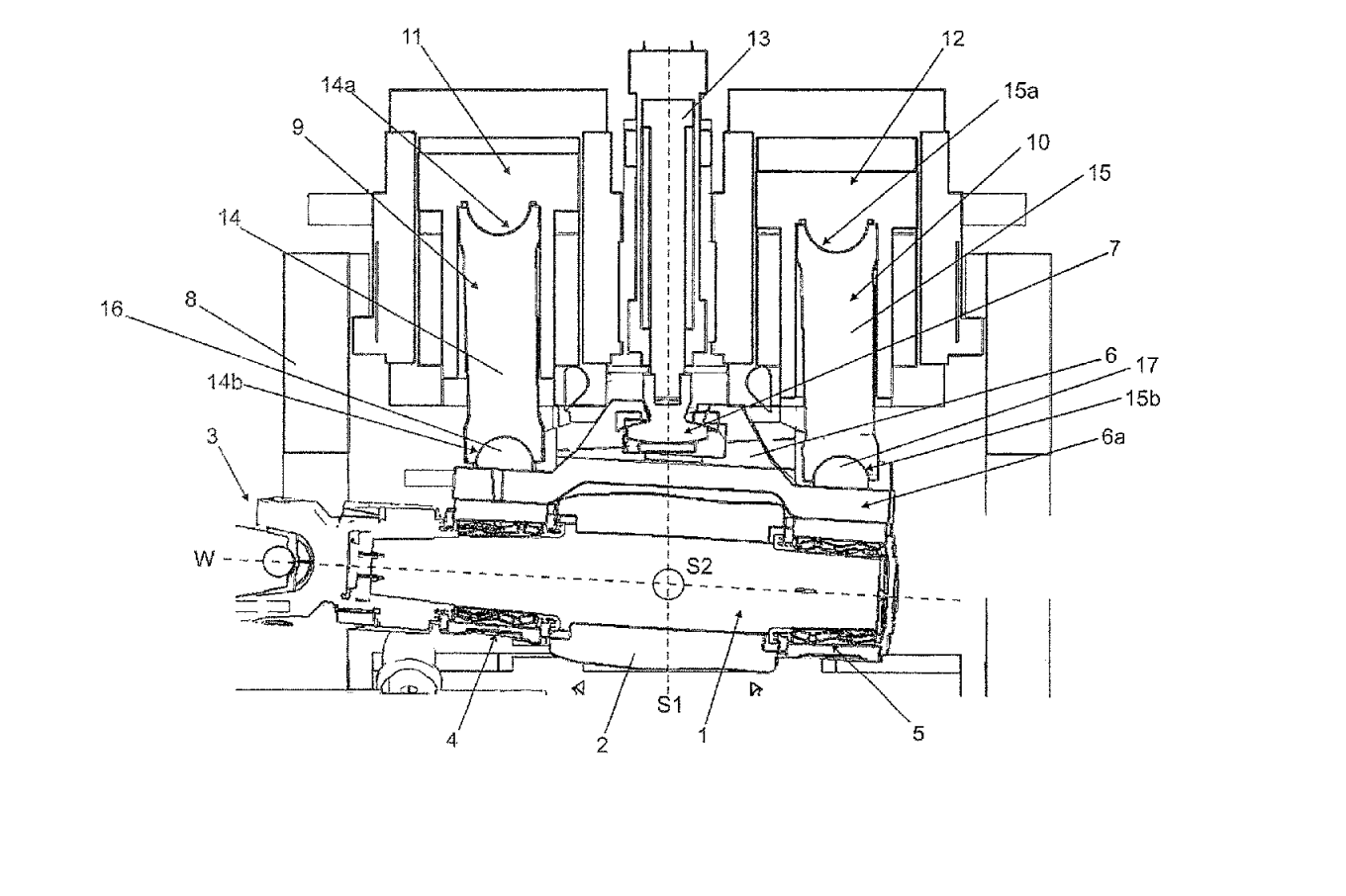
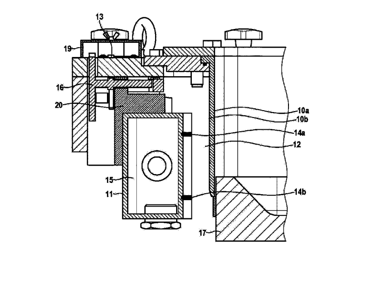
US11400498 — CROSS ROLLING MILL — SMS Group GmbH (Germany) — A cross-rolling mill, comprising: a plurality of roll shafts (1), each having a rotary bearing and applying a radially directed rolling force to a workpiece, wherein an orientation of a roll axis (w) of at least one of the roll shafts (1) is adjustable about a first adjustment axis (S1) and a second adjustment axis (S2); and an intermediate member (9, 10) arranged between the rotary bearing (4, 5) of at least one of the roll shafts and a control element (11, 12), said at least one intermediate member (9, 10) comprising a rolling force-transmitting rocker pin (14, 15) having a spherical surface (14 a, 14 b, 15 a, 15 b), said rocker pin supported via the spherical surface for pivotal movement of the rocker pin in a plurality of directions relative to the one of the roll shafts.
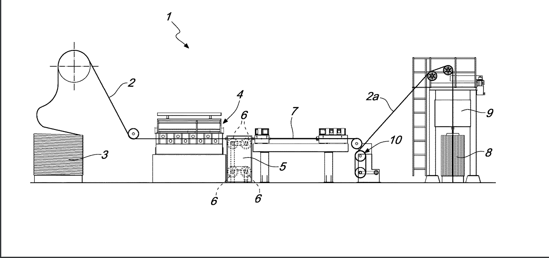
US11400500 — METHOD FOR CONVERTING WIRE ROD OF NONFERROUS METALS AND ALLOYS THEREOF TO WIRE WITH HIGH ELONGATION AND IN THE ANNEALED STATE — Giulio Properzi (Italy) — A method for converting wire rod of nonferrous metals and alloys thereof to wire with elongation and in the annealed state, in which the reduction in diameter in order to pass from wire rod with a diameter of at least 8 mm-9.5 mm to wire with a diameter of 1.5 mm-2.5 mm is carried out by way of a plastic deformation process, wherein the temperature of the metal subjected to plastic deformation is controlled in order to have, at the end of the plastic deformation process, the wire at a temperature higher than or equal to the recrystallization temperature.
US11401584 — Aluminum alloy sheet for battery lid use for forming integrated explosion-proof valve and method of production of same — Nippon Light Metal Company, Ltd. (Japan) — Aluminum alloy sheet for battery lid use for forming an integrated explosion-proof valve having a component composition containing Fe: 1.05 to 1.50 mass %, Mn: 0.15 to 0.70 mass %, Ti: 0.002 to 0.15 mass %, and B: less than 0.04 mass %, having a balance of Al and impurities, having an Fe/Mn ratio restricted to 1.8 to 7.0, restricting, as impurities, Si to less than 0.40 mass %, Cu to less than 0.03 mass %, Mg to less than 0.05 mass %, and V to less than 0.03 mass %, having a tensile strength of 95 MPa or more, having a value of elongation of 40% or more, having a recrystallized structure, having a value of (TS95-TS80) of less than -3 MPa when defining a tensile strength after cold rolling by a rolling reduction of 80% as TS80 and defining a tensile strength after cold rolling by a rolling reduction of 95% as TS95, and having a value of elongation after cold rolling by a rolling reduction of 90% of 5.0% or more.
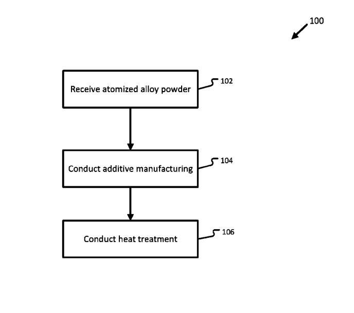
US11401585 — MULTICOMPONENT ALUMINUM ALLOYS FOR APPLICATIONS SUCH AS ADDITIVE MANUFACTURING — Questek Innovations LLC (USA) — An alloy comprising, by weight percentage: 1% to 4.2% nickel; 0.5% to 2.6% erbium; 0.1% to 1.5% zirconium; 0.05% to 0.3% yttrium; 0.1% to 1.2% ytterbium; and the balance of weight percent comprising aluminum and incidental elements and impurities, wherein the alloy includes L12 precipitates having an Al3X composition, where X is at least one of: erbium, zirconium, yttrium, and ytterbium.
US11407026 — ROLLING INGOT MOULD FOR THE CONTINUOUS CASTING OF ALUMINIUM AND ALUMINIUM ALLOYS — Casthouse Revolution Center GmbH (Austria) — Cooling system for a continuous casting mould comprising at least one cooling unit, wherein the mould has a running surface with an inner side and an outer side, and the inner side of the running surface limits a continuous casting during operation, wherein the cooling unit is designed to be moveably arranged on the mould and the cooling unit has an adjusting element, wherein the cooling unit is arranged on the mould in such a way that a gap is formed between the cooling unit and the outer side of the running surface and the width of the gap can be adjusted by the adjusting element.
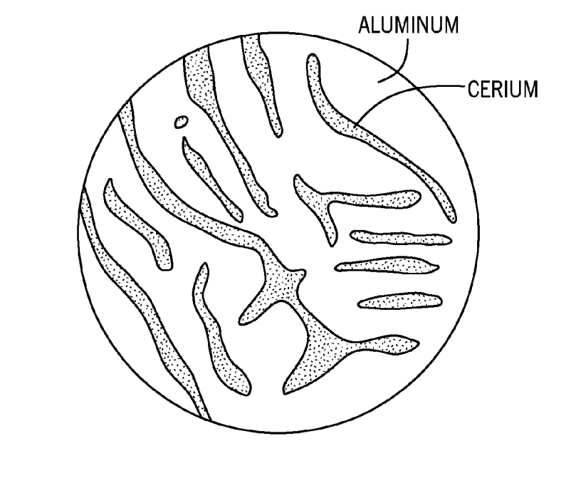
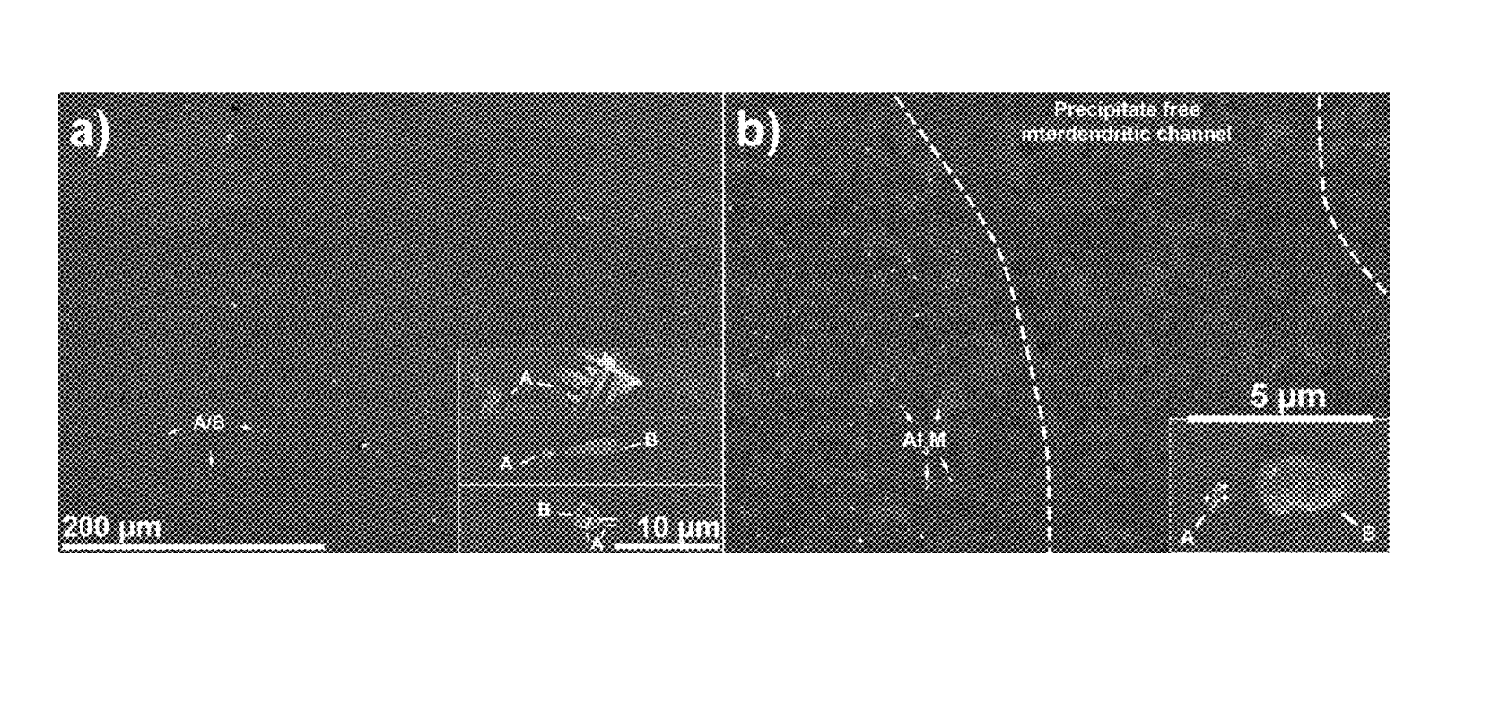
US11408056 — ALUMINUM BASED ALLOY CONTAINING CERIUM AND GRAPHITE — Intelligent Composites, LLC (USA) — A cast aluminum alloy suitable for conventional casting, comprising: an aluminum matrix; between 6 and 16 weight percent cerium distributed within the aluminum matrix; and a reinforcement phase of between 1 and 20 volume percent graphite particles distributed within the aluminum matrix, wherein said graphite particles have a thickness that is between 10 and 200 microns; wherein the aluminum and cerium form an intermetallic compound with a crystal structure, said intermetallic compound having an average thickness that is in the magnitude of hundreds of microns and an average spacing in the magnitude of microns.
US11408061 — HIGH TEMPERATURE, CREEP-RESISTANT ALUMINUM ALLOY MICROALLOYED WITH MANGANESE, MOLYBDENUM AND TUNGSTEN — Ford Global Technologies, LLC and Northwestern University (USA) — An aluminum alloy consisting of, in atom %: scandium greater than 0.0 and less than or equal to 0.15; zirconium greater than 0.0 and less than or equal to 0.35; erbium greater than 0.0 and less than or equal to 0.15; silicon greater than 0.0 and less than or equal to 0.2; at least one of molybdenum greater than 0.0 and less than or equal to 0.75 and tungsten greater than 0.0 and less than or equal to 0.35; manganese greater than 0.0 and less than or equal to 1.5; optionally iron less than or equal to 0.1; and balance aluminum.
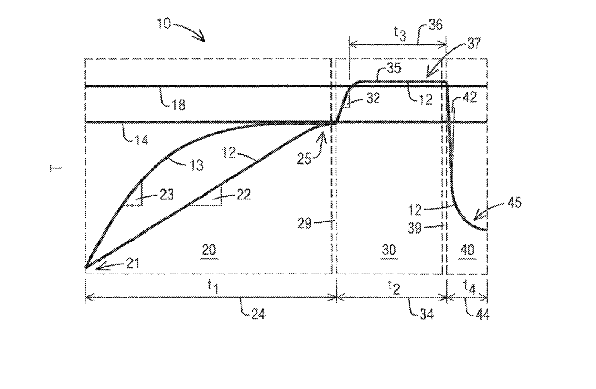
US11408062 — System and method for heat treating aluminum alloy castings — Consolidated Engineering Company, Inc. (USA) — A method for heat treating a casting formed in a high pressure die casting (HPDC) process from an aluminum alloy having a silicon constituent and a plurality of metal alloying constituents, the method comprising: identifying a predetermined silicon solution temperature at and above which a rate at which the silicon constituent enters into solid solution is accelerated so as to increase growth of internal pores within the casting; identifying a predetermined alloying metal solution temperature that is greater than the predetermined silicon solution temperature and at and above which a first metal alloying constituent of the plurality of metal alloying constituents enters into solid solution; wherein the first metal alloying constituent has the highest solution temperature of the plurality of metal alloying constituents; heating the casting to a first casting temperature less than 10° C. below the predetermined silicon solution temperature, and ensuring that substantially all of the metal alloying constituents of the plurality of metal alloying constituents of the casting are heated to a temperature equal to or greater than the first casting temperature but below the predetermined silicon solution temperature; increasing the rate of heat input into the casting to heat the casting to a second casting temperature less than 10° C. above the predetermined alloying metal solution temperature; maintaining the casting at the second casting temperature for a period of time sufficient for the casting to achieve a time-in-treatment ratio greater than about 50%, the time-in-treatment ratio being defined by a duration of time the casting spent above the alloying metal solution temperature divided by a duration of time the casting spent above the silicon solution temperature; and quenching the casting to a temperature less than about 250° C.
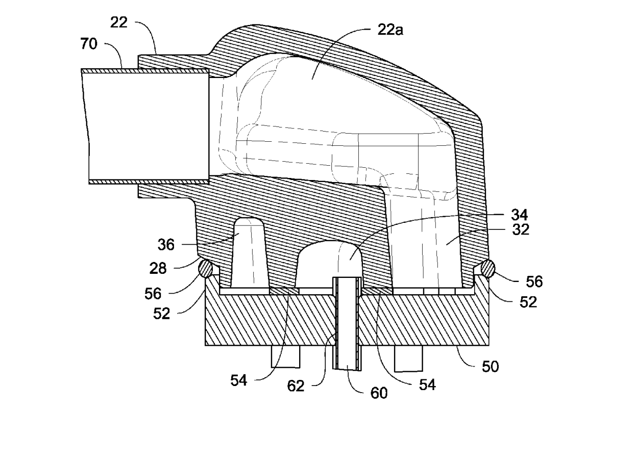
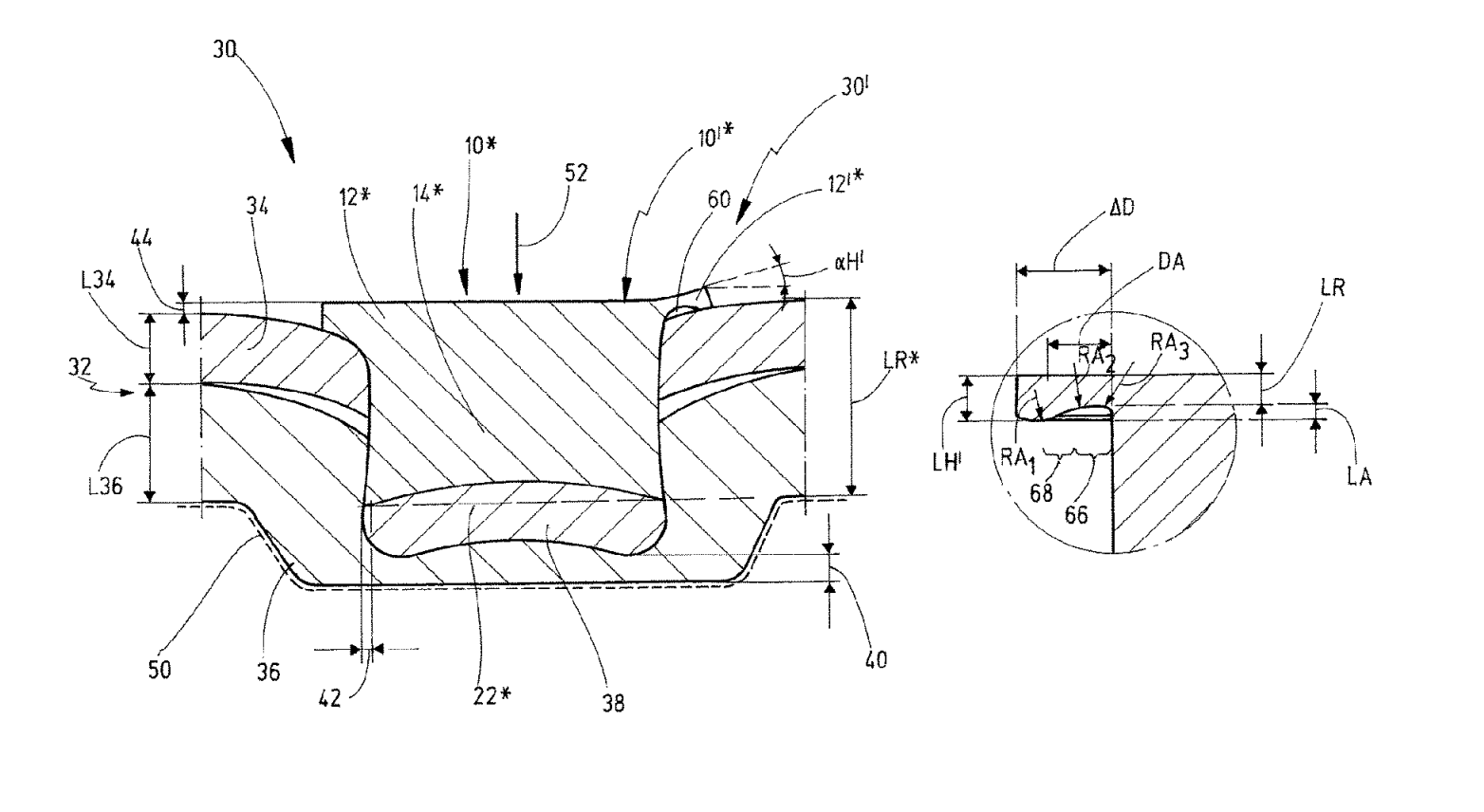
US11408457 — Self-piercing rivet and self-piercing riveted joint — NEWFREY LLC (USA) — A self-piercing rivet for joining at least two workpieces, the self-piercing rivet comprising: a head defining a head diameter (DH) and including a head bottom surface; a shank defining a shank diameter (DS), and wherein the shank, on a foot end located opposite the head partially defines an axial recess which has an axial depth (LB), and the shank also includes one of a flat surface portion or a circular cutter on the foot end; and a transition portion located between the head and the shank and partially defining an annular recess open axially downwards; and wherein the annular recess is formed by a curve including a first radius, a second radius, and a third radius; wherein the second radius and a third radius are proximate to the shank and are upward pointing; wherein the first radius is furthest outward from the shank and is downward pointing and the curve merges outwardly and continuously into the head bottom surface; wherein the first radius connects to the second radius; wherein the first radius, the second radius, and the third radius transition such that the annular recess has a continuous form; and wherein the annular recess is formed such that a portion of the head protruding radially in relation to the shank is able to be bent in relation to a virtual radial plane, about a virtual circular rotational axis during a self-piercing riveting operation.
US11413669 — LOCALLY CHANGING THE ROLL GAP IN THE REGION OF THE STRIP EDGES OF A ROLLED STRIP — Primetals Technologies Gmbh (Germany) — A method for locally increasing a size of a roll gap in a region of strip edges of a rolled strip in a rolling stand, wherein the rolling stand comprises: an upper working roller and a cooperating lower working roller, the rollers extending parallel to each other and defining a gap between the rollers, the rollers cooperating for passage of the rolled strip through the gap between the rollers; each working roller having two opposite ends configured for rotational mounting of the working roller; each working roller having, in a respective axial direction thereof, a conical portion followed by a running surface; the upper working roller is oriented in an opposite axial direction to the lower working roller; each working roller having a respective separate displacing device configured and operable for axially displacing the respective working roller; the method comprising: determining a radial wear Δr of the running surface of at least one of the working rollers in a radial direction thereof, and hot rolling a rolled stock in the rolling stand through the gap between the rollers, and causing the radial extent of the running surface of at least one of the working rollers to decrease by Δr during the rolling, while axially displacing the working rollers in opposite axial directions by a displacement distance s > (Δr/tan(α)) where α indicates a pitch angle of the conical portion of the respective working roller.
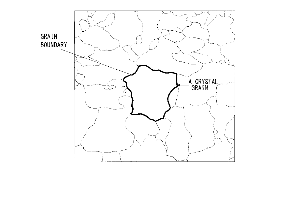
US11408690 — Method for producing aluminum alloy clad material — UACJ CORPORATION (JAPAN) — A method for producing an aluminum alloy clad material having an aluminum alloy core material and a sacrificial anode material clad on at least one surface of the core material, comprising: a step of casting the aluminum alloys for the core material and the sacrificial anode material, respectively, a hot rolling step of hot rolling a cast sacrificial anode material ingot to a predetermined thickness, a cladding step of cladding the sacrificial anode material rolled to the predetermined thickness on at least one surface of a core material ingot obtained by casting the aluminum alloy for the core material and thus obtaining a clad material, a hot clad rolling step of hot rolling the clad material, a cold rolling step of cold rolling the hot-rolled clad material, and one or more annealing steps of annealing the clad material either during or after the cold rolling step or both during and after the cold rolling step: wherein in the hot clad rolling step, the rolling start temperature is 400 to 520° C., and the number of rolling passes each with a rolling reduction of 30% or more is restricted to one to five while the temperature of the clad material is 200 to 400° C., and the clad material is held at 200 to 560° C. for 1 to 10 hours in the annealing step(s), wherein the core material comprises an aluminum alloy comprising 0.05 to 1.50 mass % Si, 0.05 to 2.00 mass % Fe, 0.50 to 2.00 mass % Mn and a balance of Al and unavoidable impurities based on a total mass of the core material, the sacrificial anode material comprises an aluminum alloy comprising 0.50 to 8.00 mass % Zn, 0.05 to 1.50 mass % Si, 0.05 to 2.00 mass % Fe and a balance of Al and unavoidable impurities based on a total mass of the sacrificial anode material, a grain size of the sacrificial anode material is 60 vim or more, and a ratio R1/R2 is 0.30 or less, when R1 (µm) is a grain size in a thickness direction and R2 (µm) is a grain size in a rolling direction in a cross section of the core material along the rolling direction.
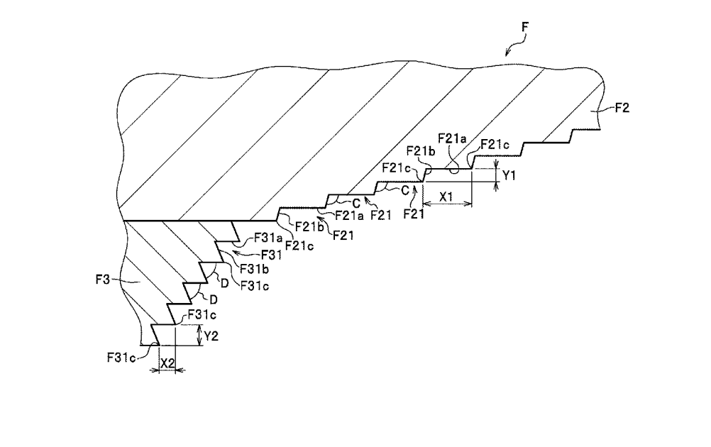
US11413700 — Method for manufacturing heat transfer plate — NIPPON LIGHT METAL COMPANY, LTD. (JAPAN) — A method for manufacturing a heat transfer plate, comprising: a heat medium pipe insertion process to insert a heat medium pipe into a concave groove formed in a bottom face of a lid groove which opens to a front face of a base member; a lid plate insertion process to insert a lid plate into the lid groove; and a joining process to perform friction stirring while a rotary tool provided with a base side pin and a tip side pin is moved along a butted portion formed by a side wall of the lid groove and a side face of the lid plate being butted against each other, wherein a taper angle of the base side pin of the rotary tool is 135 to 160 degrees and is larger than another taper angle of the tip side pin, wherein a stepwise step portion is formed on an outer circumferential face of the base side pin, wherein a helical groove is formed on an outer circumferential face of the tip side pin, the helical groove being formed of a helical bottom face and a helical side face, wherein an angle defined by the helical bottom face and the helical side face is 45 to 90 degrees, wherein the helical bottom face of the helical groove adjoins the helical side face of the helical groove at an outer side of the tip side pin, and the helical side face of the helical groove adjoins the helical bottom face of the helical groove at an inner side of the tip side pin, and wherein in the joining process, friction stirring is performed while the tip side pin of the rotary tool which is rotating is inserted into the butted portion and the outer circumferential face of the base side pin is in contact with the base member and the lid plate, and plastically fluidized material fluidized by frictional heat is flowed into a void portion formed adjacent to the heat medium pipe.
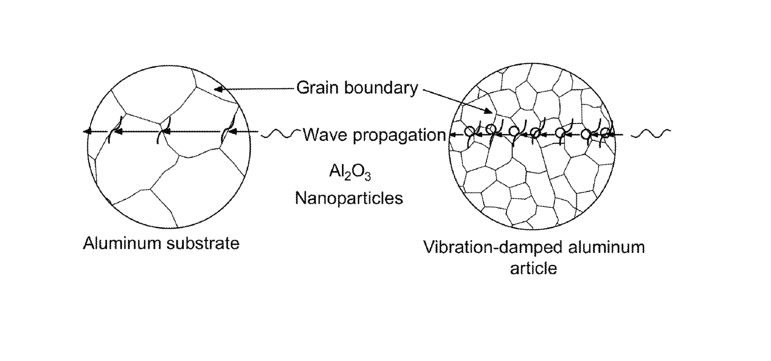
US11413701 — Vibration-damped aluminum article and method of forming the article — King Abdulaziz University (Saudi Arabia) — A method of improving vibration damping in an aluminum article, the method comprising: forming a groove in a surface of an aluminum substrate, the groove having a groove depth which is less than 50% of a thickness of the aluminum substrate; placing metal oxide nanoparticles in the groove to form an unmixed composite; and friction stir processing the unmixed composite to form a vibration-damped aluminum article, wherein the friction stir processing comprises at least two passes over the unmixed composite, wherein the vibration-damped aluminum article comprises a surface nanocomposite portion and an aluminum alloy portion, wherein the metal oxide nanoparticles are substantially free of metal carbides, metal borides, and carbon nanomaterials, wherein the metal oxide nanoparticles are present in a range of from 0.5 to less than 10 vol %, based on a total volume of vibration-damped aluminum article, wherein the vibration-damped aluminum article has a damping ratio in a range of from 3.0 to 17.0%, and wherein the vibration-damped aluminum article has a loss factor in a range of from 0.06 to 0.30 and a loss modulus (E”) in a range of from 4.0 to 9.0.
US11414730 — Magnesium alloys, bicycle rims, and preparation methods — JURNONG BAILEY MAGNESIUM ALLOY MATERIAL TECHNOLOGY CO., LTD. (China) — A magnesium alloy, comprising the following components in percentage by weight of the magnesium alloy: 5.5-6.0% of Zn, 0.3-0.6% of Zr, 0.5-2.0% of a yttrium-rich mixture of rare earth metals, and the balance of Mg, and wherein the yttrium-rich mixture includes the following components in percentage by weight of the yttrium-rich mixture: 25-30% of Y, 15-20% of Nd, 12-16% of Gd, 10-15% of Dy, 8-12% of La, 6-10% of Ce, 3-6% of Pr, 2-5% of Ho, 1-3% of Er, and the balance of other rare earth metals.
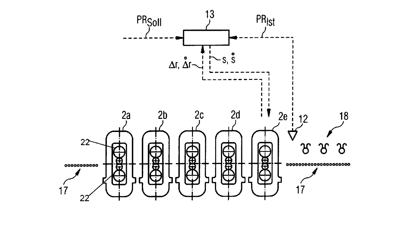
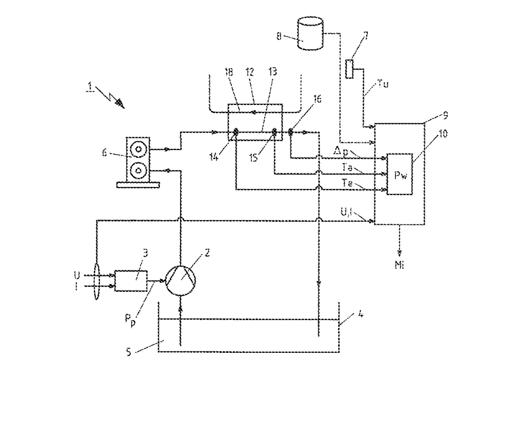
US11415156 — Method for monitoring the condition of a hydraulic system of a metal forming plant and condition-monitoring device — SMS group GmbH (Germany) — A method for monitoring a condition of a hydraulic system of a metal forming plant (1), wherein the hydraulic system is coupled to or provided with a pump (2) drivable by a drive motor (3) for providing a working fluid in the hydraulic system and with a heat exchanger (12), a primary side (13) of which is flowed through by the working fluid and a secondary side (18) of which is provided with a cooling fluid for absorbing a part of a heat energy of the working fluid, wherein the method comprises the following steps initiated by or carried out by a condition-monitoring device (9) during operation of the hydraulic system: a) determining (S1) a current cooling power (Pw) of the heat exchanger (12); b) determining (S2) a current conveying power (Pp) of the pump (2); and c) determining (S4) a current maintenance urgency and/or a current ageing condition of the hydraulic system (Mi) based on the determined current cooling power (Pw) of the heat exchanger and the determined current conveying power (Pp) of the pump.
US11415381 — Heat exchanger with aluminum tubes rolled into an aluminum tube support — TRANE INTERNATIONAL INC. (USA) — A method of assembling a heat exchanger, comprising: mechanically rolling end portions of aluminum tubes into openings of an aluminum tube support through which the openings extend; expanding the end portions of the aluminum tubes into the openings of the aluminum tube support to thereby create a mechanical connection between the aluminum tubes and the aluminum tube support, wherein the mechanical connection is an interference fit and is free from welds or brazing; sealing the mechanical connection between the aluminum tubes and the aluminum tube support, and assembling a manufactured manifold to the aluminum tube support, wherein the manufactured manifold comprises a gas header, an intermediate header, a liquid header, and return bends.