Compiled and edited by Joseph C. Benedyk.
U.S. Patents
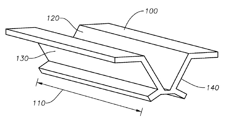
US9905214 — EXTRUDED SONAR CHASSIS — Navico Holding AS (Norway) — An aluminum transducer chassis prepared by a process having the following steps: performing an extrusion using a die and an aluminum billet to create an extruded chassis, wherein the die has a cross sectional shape of the transducer chassis; and cutting the extruded chassis to a plurality of predetermined lengths, each length corresponding to the length of a transducer chassis.
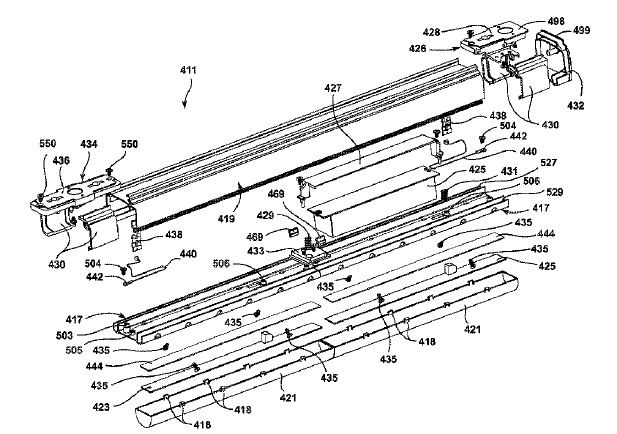
US9897294 — COMMERCIAL LIGHTING INTEGRATED PLATFORM — Tempo Industries, LLC (USA) — One or more interconnectable modules, each comprising a housing mounting an LED circuit board on an underside thereof and having a guide track on a top surface thereof with one or more slip fitter components shaped to slidably insert into and engage or attach to the guide track and configured to cooperate with one or more of a ceiling mounting bracket, a hanger bracket, an eye hanger and a cable hanging arrangement in order to provide multiple modes of hanging, suspending or otherwise mounting the one or more lighting modules. In one illustrative embodiment, the bottom cover components comprise two identical die cast clear anodized aluminum sections, while the upper housing 419 is a single piece aluminum extrusion, fabricated, for example, of 6063-T6 material with a clear anodized finish.
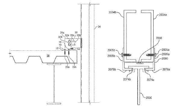
US9896840 — CURTAIN WALL MULLION ANCHORING SYSTEM — Advanced Building Systems, Inc. (USA) — Curtain wall mullion anchoring systems for resisting dead load and negative wind load, and that permit three-way construction tolerance adjustments. The mullion anchoring systems include an anchoring device secured to a building structural element and attached to a mullion connection bridge, which is connected to a mullion connection clip, which is connected to a mullion. Uplifting forces on the anchoring device may be significantly reduced or even eliminated by transmitting dead load under negative wind load conditions from the mullion to the anchoring device at a point over the inside of a concrete floor slab, such that the dead load counteracts any uplifting force generated by the negative wind load.
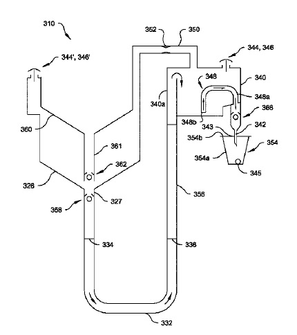
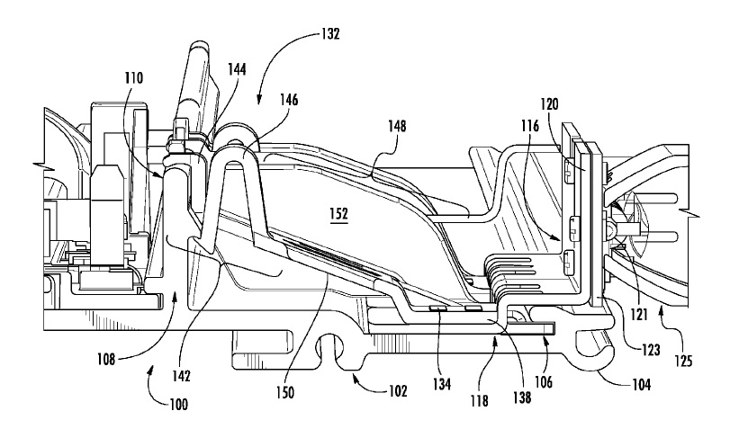
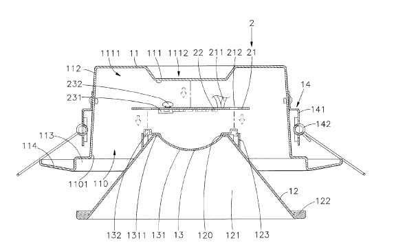
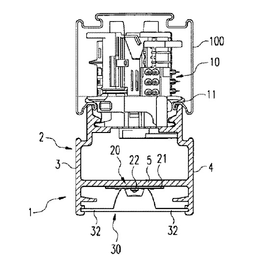
US9888807 — KITCHEN APPLIANCE FOR PREPARING A BEVERAGE AND METHOD OF OPERATING SAME — Hamilton Beach Brands, Inc. (USA) — A kitchen appliance includes a first reservoir for receiving a liquid to be used for preparing a beverage. A hot water generator (`HWG`) has an inlet end, an outlet end and a passageway extending therebetween. The HWG is a U-shaped, tubular, aluminum extrusion with a cal-rod, with the inlet end of the HWG being connected to the first reservoir. Liquid from the first reservoir flows into the HWG through the inlet end. A second reservoir is connected to the outlet end of the HWG. The second reservoir includes a discharge port, a gas vent and a skirt extending from a wall of the second reservoir further than the gas vent. The skirt at least partially surrounds the gas vent. At least a portion of the skirt is spaced laterally inwardly from an outer sidewall of the second reservoir.
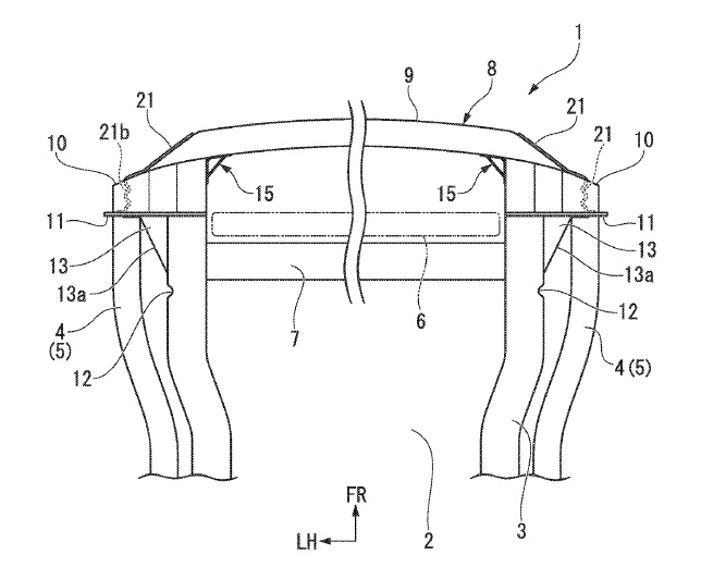
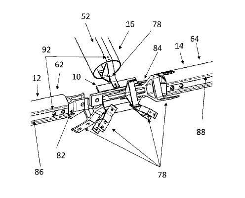
US9884599 — VEHICLE FRONT STRUCTURE — Honda Motor Co., Ltd. (Japan) — A vehicle front structure includes a front frame member, a bumper beam (9) disposed at a front section of the vehicle in a vehicle width direction, a crush box (10) fixed to a rear surface of the bumper beam (9) and having a rear end portion coupled to a front end portion of the front frame member, and a corner reinforcement member (15), easily manufactured as an aluminum extrusion, disposed at a corner portion formed between the rear surface of the bumper beam (9) and the side surface of the crush box (10), wherein an outer surface of the corner reinforcement member (15) is joined in a state in which the outer surface abuts the rear surface of the bumper beam (9) and the side surface of the crush box (10).
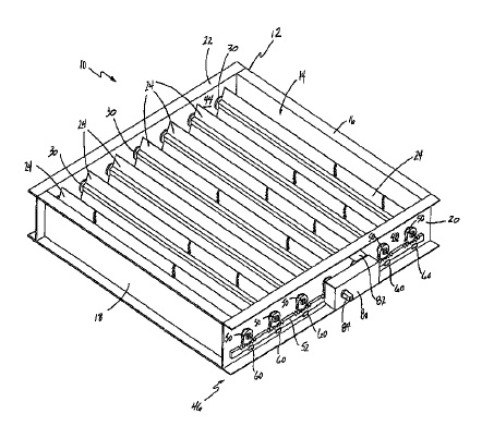
US9877928 — GEAR DRIVE DAMPER — Air Systems, Inc. (USA) — An air damper assembly for regulating an air flow includes a frame, a plurality of elongated damper blades rotatably mounted to the frame, and a drive mechanism for actuating the damper blades between open and closed positions. The frame and damper blades can be formed as aluminum extrusions. The drive mechanism includes a gear fixedly secured to a distal end of each of the damper blades and an elongated rack slidably coupled to the frame. The rack meshingly engages the gears such that linear movement of the rack in a first linear direction results in rotational movement of the damper blades in a first rotational direction and linear movement of the rack in a second linear direction opposite the first linear direction results in rotational movement of the damper blades in a second, rotational direction opposite the first rotational direction.
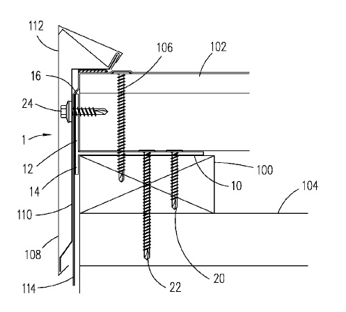
US9874023 — FASCIA MOUNTING BRACKET — Metal-Era, Inc. (USA) — A fascia mounting bracket preferably includes a base member and a vertical attachment flange. The base member extends outward in a horizontal orientation from the vertical attachment flange. A lower portion of the vertical attachment flange extends below the base member and an upper portion of the vertical attachment flange extends above the base member. A plurality of staggered fastener openings are preferably formed through the base member. The fascia mounting bracket is preferably fabricated from an aluminum extrusion. The base member is inserted between a top of a nailer and a bottom of an insulation board. The fascia mounting bracket is secured to a building with a plurality of fasteners inserted through the plurality of fastener openings and screwed into the nailer. Fascia trim is attached to the top portion of the vertical attachment flange with a plurality of self-tapping fasteners.
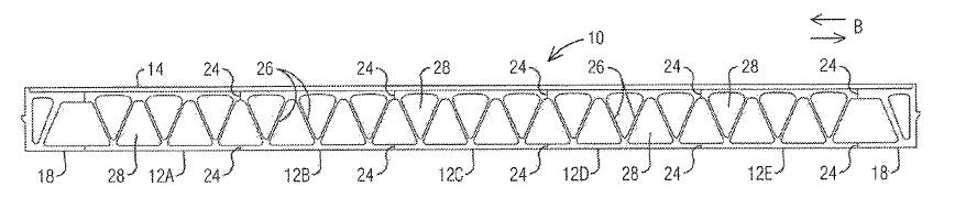
US9863103 — MODULAR BRIDGE DECK SYSTEM CONSISTING OF HOLLOW EXTRUDED ALUMINUM ELEMENTS — AlumaBridge, LLC (USA) — A modular bridge deck system supported on a plurality of cooperating girders and the deck system that comprises a plurality of deck panels secured together to form a modular bridge deck. Each deck panel is preferably formed by longitudinally shop friction-stir welding a plurality of elongated, multi-void, extruded aluminum structural elements. A top surface of each respective deck panel and the longitudinal shop-welding form a substantially continuous top surface of the modular bridge deck. In addition, the modular bridge deck has a depth and weight that is substantially equal to a weight of a steel open-grid deck of a moveable bridge or fixed span bridge to be replaced by the modular bridge deck system.
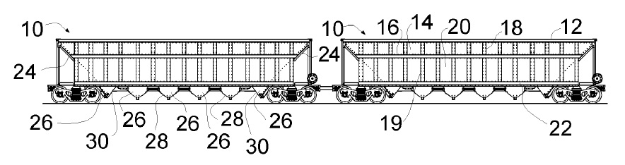
US9862393 — OPEN TOP HOPPER RAILCAR WITH BIASED DOOR SEAL AND ENLARGED CONTOURED END DOOR — Jac Operations, Inc. (USA) — A railroad open top hopper car comprises a pair of spaced trucks a railcar body, the body comprising a pair of side structures railcar, wherein each including (i) a top chord extending the side structure length, (ii) a plurality of upper side stakes extending from the top chord, (iii) an intermediate side chord extending the side structure length and below the top chord and coupled to the upper side stakes, (iv) a plurality of lower side stakes extending from the intermediate side chord, and (v) a side sill extending the length and below the intermediate side chord and coupled to the lower side stakes. All of these structural elements can be manufactured from aluminum extrusion. The body forms discharge chutes forming pockets for the body with a plurality of intermediate doors and end doors, wherein the end doors are larger than the intermediate doors. Each door may include a biased door seal.
US9857037 — ASSEMBLING STRUCTURE FOR LED LUMINAIRE — GLT Corporation (Taiwan) — The present invention provides an assembling structure for LED luminaire, including a main support, at least one LED luminaire and at least one connecting part. The main support which may be an aluminum extrusion includes front faces on radial side, slide tracks on the front faces, and two side faces. The LED luminaire includes a cap-like housing and a lamp-connecting portion. The connecting part includes a first locating block provided in one slide track, a second locating block passing through each side face and provided in another slide track different from that for the first locating block, and a support body connected with the first and second locating blocks while extending far away from the main support. The support body is connected, at one end far away from the first and second locating blocks, with the lamp-connecting portion, while the connecting part and LED luminaire are pivoted with respect to the main support.

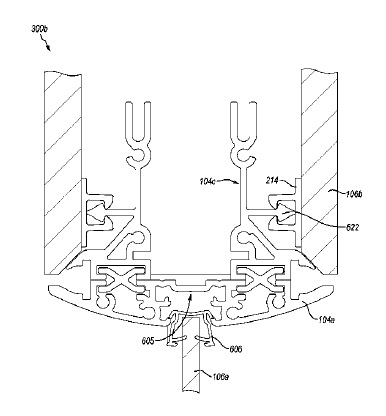
US9856644 — STRAIGHT AND CURVED RECONFIGURABLE PARTITION SYSTEMS — DIRTT Environmental Solutions, Ltd. (Canada) — A reconfigurable modular partition system having a plurality of different types of interchangeable (wall or ceiling) modules with different types of compatible connection components, each connection component being configured to align with another connection component at an interface to form an interface connection (e.g., channel) for securing the connection components together with one or more universal connection interface members. The connection components can be fabricated from aluminum extrusion with desired profiles that can crease attributes, functionality, utility, and structural properties unique to each connection component. The interface is configured for on-demand reconfiguration without laborious alteration to aspects of the partition system, modules, and components thereof. Reconfiguration of modules is facilitated by removing the universal connection interface member from the channel, thereby releasing the attachment mechanism and allowing rearrangement of the module(s). Replacement of the universal connection interface member secures the reconfigured modules in place in the rearranged partition system.
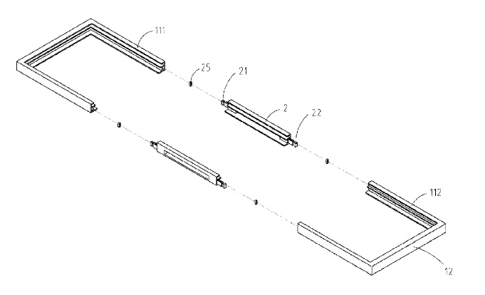
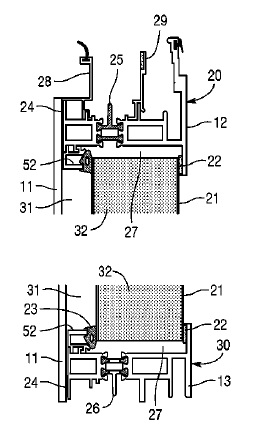
US9853598 — SOLAR MODULE FRAME — NEO Solar Power Corp. (Taiwan) — A solar module frame includes two first borders and two second borders. At least one first border includes a first segment and a second segment, where one end of the first segment is connected to one end of the second border, and one end of the second segment is connected to one end of the other second border. The solar module frame includes at least one connection component. The first and second border and the connection component can be made of metal, plastic, or other material. One end of the connection component is connected to the other end of the first segment, and the other end of the connection component is connected to the other end of the second segment. Each of the first segment, the second segment, and the connection component includes an external wall, a support wall, a first clamping wall, and a second clamping wall. Each of the first segment and the second segment includes an internal wall.
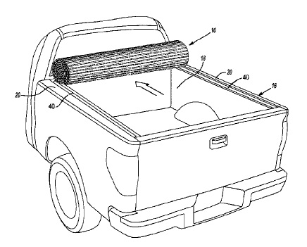
US9840135 — HARD ROLL-UP TONNEAU — Truxedo, Inc. (USA) — A tonneau system for a pickup bed comprising a bracket system connectable with a sidewall of the pickup bed and a plurality of hingeable sections pivotally coupled to each other to define a continuous surface. Each of the plurality of hingeable sections being connected to adjacent hingeable sections to permit at least some of the plurality of hingeable sections to be rolled together into a generally circular cross-section to selectively reveal the pickup bed. In some embodiments, hingeable sections are made of an interlocking aluminum extrusion that can be adhered or otherwise coupled to a covering material. In some embodiments, the covering material can be made of vinyl and can be continuous along the plurality of hingeable sections, thereby forming a continuous sheet.
US9837759 — WIRESTRAIN RELIEF TO USE ON A LIGHT EMITTING DIODE LINEAR MODULE — GE Lighting Solutions, LLC (USA) — Provided is a connection housing including a first plate having a connecting member for slidably connecting the first plate to an electrical assembly. The first plate includes a ridge portion formed across a threading path. A second plate has an opening for non-slidably connecting the second plate to the electrical assembly. The second plate includes a valley portion positioned in opposing relation to the ridge portion. The first and second plates are configured for (i) facilitating placement of a wire along the threading path and (ii) folding onto each other to restrict movement of the wire after the folding. The strain relief device can slide on a built-in feature on an extruded heat sink constructed, for example, of aluminum.
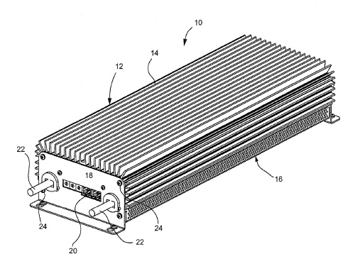
US9821702 — WARNING LIGHT ASSEMBLY — Whelen Engineering Company, Inc. (USA) — A warning light for attachment to a vehicle comprising a thermally conductive longitudinally extending base, in one embodiment made of an aluminum extrusion, a plurality of light head mount assemblies, a plurality of LED warning light assemblies, and a plurality of electronic control circuits. Said base has a pair of generally parallel longitudinal edges and a pair of ribs projecting perpendicularly from said base. Said light head mount assemblies comprise a bracket and a light head retention shoe. Said bracket has a generally planar bracket first portion and a generally planar bracket second portion oriented perpendicular to said first portion. Said light head shoe has a sole configured to engage said bracket first portion, a rib engaging portion, and a brace extending angularly therebetween. Said LED assemblies are mounted on said bracket second portion. Said dome has a main body portion, sidewalls configured to engage said edges, and end walls.
US9821574 — MEDIUM HOLDING DEVICE AND RECORDING APPARATUS — Seiko Epson Corporation (Japan) — A medium holding device includes a large tray having a medium mounting surface; an intermediate tray having a medium mounting surface smaller than that of the large tray; a tray mounting section on which the large tray and the intermediate tray are selectively mounted; a frame body, configured from aluminum extrusions, that holds a recording medium with the large tray if the large tray and the intermediate tray have separate configuration and the large tray is mounted on the tray mounting section; and a first attachment that is mounted on an inside of the frame body and holds the recording medium with the intermediate tray if the intermediate tray is mounted on the tray mounting section, and is separated from the frame body if the large tray is mounted on the tray mounting section.
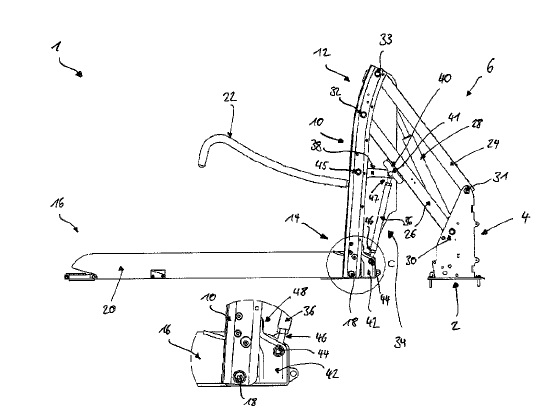
US9814635 — VEHICLE LIFT — AMF-Bruns GmbH & Co. KG (Germany) — A vehicle lift for a load, such as a wheelchair. The whole lift is movable between a retracted position and an extended position that comprises a support pillar, a platform, and a lifting device. The platform is connected pivotably to the support pillar and has a horizontal pivot axis such that the platform is pivotable about the horizontal axis. The lifting device is hingedly connected to the support pillar and is configured for lifting and lowering the support pillar with the platform between the retracted position and the extended position. The support pillar is one piece and has a curved configuration along the longitudinal axis. The support pillar is formed integrally as a seamless one piece through steps including extrusion and bending, has a curved portion extending along an arcuate path relative to the longitudinal axis with a bending radius of between 700 mm and 1000 mm measured at an inner edge of the support pillar, and is comprised of aluminum.
US9808060 — PULL HANDLE OF LUGGAGE — C & C Luggage Manufacturing Co., Ltd. (China) — A pull handle of a luggage, which is adapted for accommodating a control device having a button, includes a main body and a cover. The main body has a transverse pipe, two vertical pipes integrally extended from two ends of the transverse pipe respectively, and a hollow portion located at the transverse pipe. The cover is mounted to the main body and covers at least one part of the hollow portion. The cover and the transverse pipe constitute a grip which has an opening corresponding in position to the button of the control device. In this way, the pull handle is not only firm in structure so as to be uneasily damaged and have long life time, but also simplified in assembling process. In the process of manufacturing the main body 10, a straight hollow tube is made by aluminum extrusion, partially removed to form the hollow portion 15, and then bent to become the main body 10. The hollow portion 15 makes the straight tube more easily bent to become the main body 10, and the control device 2 can be installed into the main body 10 through the hollow portion 15.
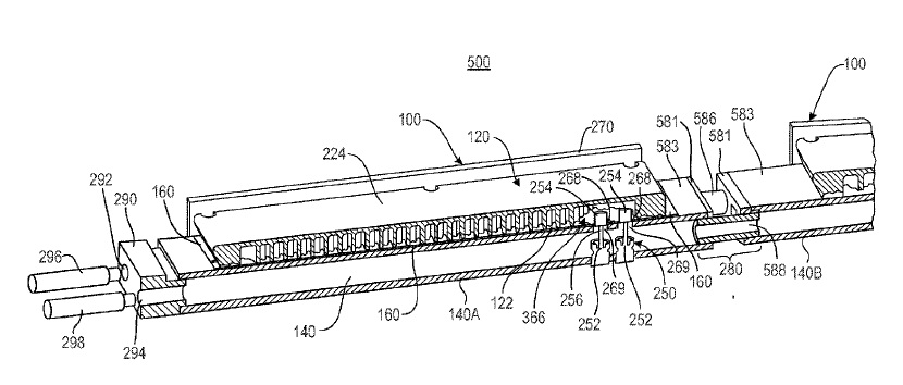
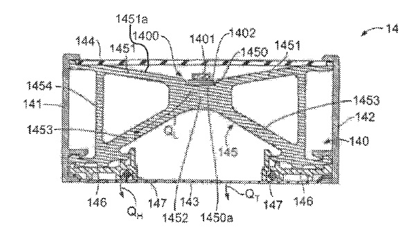
US9803937 — LIQUID COOLING — Hewlett Packard Enterprise Development LP (USA) — An assembly for liquid cooling of electronic devices is provided herein. The assembly includes a thermal member, a support member made of an aluminum extrusion with inlet and outlet channels or cavities formed therein, and a gasket. The thermal member includes an array of cooling pins formed of a thermally conductive material to extend from the thermal member. The support member includes an inlet channel and an outlet channel. The inlet channel to provide a fluid to the array of cooling pins. The outlet channel to receive the fluid from the array of cooling pins. The gasket between the thermal member and the support member to form a cooling channel with a fluid tight seal therebetween. The support member 140 may further include additional structural members, such as a guide structure formed in the aluminum extrusion to position the support member as it is being inserted into a rack or shelf in alignment with the compute module.
US9797185 — SELF-LOCKING HANDRAIL SYSTEM — City Glass & Glazing (P) Ltd. (India) — The current disclosure relates to a unique and compact self-lock glazing system composed of two aluminum extrusion profiles, a male profile and a female profile, designed in such a way to self-lock glass panels using beadings. The female profile includes a first leg, a first locking extension that is approximately parallel to the first leg, having a gap formed therebetween, and a first vertical leg extending from the first locking extension approximately orthogonal to the first locking extension. The male profile includes a second vertical leg, and a second locking extension extending from a free end of the second locking extension, forming a fulcrum. A panel is positioned between the first vertical leg and the second vertical leg. A bar is positioned between the panel and the second vertical leg, the bar having first and second surfaces opposite one another that are not parallel with one another, causing the female and male profiles to engage by tilting the second vertical leg outward from the panel and about the fulcrum.
US9795245 — KITCHEN APPLIANCE FOR PREPARING A BEVERAGE AND METHOD OF OPERATING SAME — Hamilton Beach Brands, Inc. (USA) — A kitchen appliance includes a first reservoir for receiving a liquid to be used for preparing a beverage and a hot water generator (`HWG`) which is a U-shaped, tubular aluminum extrusion, with an inlet end, an outlet end and a passageway therebetween. The inlet end of the HWG is connected to the first reservoir. Liquid from the first reservoir flows into the HWG through the inlet end. A second reservoir is connected to the outlet end of the HWG. The second reservoir includes a discharge port. A fluid path connects the first and second reservoirs and bypasses the HWG. The kitchen appliance is operable for both pressurized brew/heat cycles and un-pressurized brew/heat cycles.
US9791111 — LED LIGHTING DEVICE HAVING A PROLONGED LIFE DURING HIGH TEMPERATURE OPERATION — Chicony Power Technology Co., Ltd. (Taiwan) — LED lighting device includes LED light housing including hollow outer shell made from an aluminum extrusion with a planar mounting surface, defined inner top side of accommodation chamber to face toward bottom opening, a reflector cup mounted accommodation chamber, defining conical reflective surface therein, and a carrying lens at the top center thereof with the light exit surface of lens facing the toward bottom opening of hollow outer shell. The LED light-emitting module includes a circuit board mounted between a planar mounting surface and lens, an array of LEDs arranged front side of circuit board, and a control circuit with driver IC and capacitor thereof respectively arranged opposing the front and back sides of a circuit board for converting input AC power into stabilized DC power for driving LEDS. This structural design effectively increases the available surface area of the circuit board for a circuit layout and related circuit layout insulation distance, allows installation of relatively larger amounts of LEDs to increase overall brightness, and makes the reflector cup replaceable.
US9784441 — COMPACT A.C. POWERED LED LIGHT FIXTURE — Tempo Industries, LLC (USA) — A compact LED light fixture includes an LED circuit board whose top surface mounts one or more LED’s and an A.C. LED Driver circuit. An input circuit board is mounted on an underside of the mounting platform. Unconditioned A.C. power from electrical cables positioned in a wire way, in one embodiment made of an aluminum extrusion, conducted by an electrical connector to the top surface of the LED circuit board, then across and down through the top surface of the LED circuit board to the input circuit board where the A.C. power is conditioned and then conducted back through the LED circuit board to the A.C. LED driver.
US9775207 — CONFIGURABLE LED DRIVER/DIMMER FOR SOLID STATE LIGHTING APPLICATIONS — Lumastream Canada ULC (Canada) — The disclosure is directed at a method and apparatus for configuring and powering light fixture loads for a LED low voltage distribution system. The method and apparatus include converting power being supplied for powering the set of light fixture loads and then limiting this converted power to a set of multiple current outputs supplied to the light fixture loads. The multiple current outputs are then split or regrouped prior to being delivered to the light fixture loads. In another aspect of the present disclosure, the configurable power source is housed in a rectangular enclosure with a monolithic aluminum extrusion and a U-shaped aluminum chassis and metal end plates. Various electrical components are thermally coupled to the heatsink to increase or maximize heat transfer to the outside surface of the enclosure.
US9771663 — ANODIZATION SEALING PROCESS FOR AN ALUMINUM OR ALUMINUM ALLOY ELEMENT FOR VEHICLES — Jiaxing Xinghe Automotive Parts Co., Ltd. (China) — The invention discloses an anodization sealing process for an aluminum or aluminum alloy element for vehicles, including the steps for rinsing with pure water, electrolysis, rinsing once again, electrical deposition sealing, rinsing with pure water several times and baking. The aluminum or aluminum alloy element for vehicles obtained thus has improved alkali resistance and erosion resistance.
US9767941 — SUPERCONDUCTING POWER TRANSMISSION SYSTEM AND COOLING METHOD — Chubu University Educational Foundation (Japan) and JGC Corporation (Japan) — A superconducting power transmission system that comprises an inner pipe housing a superconducting cable therein, a radiation covering at least a part of the inner pipe from outside, and an outer pipe housing the inner pipe and the radiation shield therein. A vacuum is created in a space from an inside of the outer pipe to an outside of the inner pipe with the radiation shield therebetween. The system further comprises at least one radiation shield pipe, housed in the outer pipe and thermally coupled with the radiation shield, a liquefied natural gas (LNG) as a second cryogen for the radiation shield being made to flow through the radiation shield pipe. The radiation shield 13 outside the inner pipe 12 is not a pipe but is structured with a plurality of annular members made of aluminum extrusions.

US9763526 — LED LIGHT FIXTURE ASSEMBLY WITH ELONGATED STRUCTURAL FRAME MEMBERS — ElectraLED, Inc. (USA) — An LED light fixture assembly includes an elongated first support member, an elongated second support member spaced from and substantially parallel to the first support member, and a plurality of elongated LED lighting fixtures coupled to and extending between the first support member and the second support member. Each LED lighting fixture includes an elongated structural frame member, preferably made of an aluminum extrusion, having a substantially channel shaped support portion, and a mounting portion opposite the support portion. Each LED lighting fixture also includes a plurality of LED light modules secured to and positioned along the mounting portion, and a cover extending along and supported by the mounting portion. The cover is positioned so light emitted from the plurality of LED light modules passes through the cover and away from the mounting portion.
US9752800 — NODE, SUPPORT FRAME, SYSTEM AND METHOD — Werner Extrusion Solutions LLC (USA) — A node for connecting together aluminum extrusions comprising at least a first support element, a second support element and a third support element of a support frame such as a solar frame which supports solar reflectors. A method for connecting together at least a first support element, a second support element and a third support element of a solar frame which supports solar reflectors. A system for supporting solar reflectors includes a first support frame upon which the solar reflectors are disposed. A method for forming a support frame for solar reflectors. A system for constructing a support frame from parts, including chords, for solar reflectors. A method for constructing a support frame for solar reflectors. A support frame for solar reflectors.
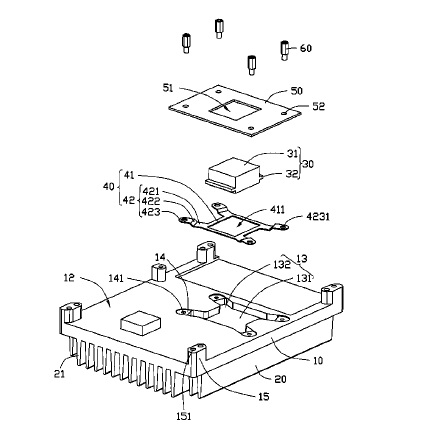
US9748161 — HEAT DISSIPATION DEVICE — Foxconn Technology Co., Ltd. (Taiwan) — A heat dissipation device includes a base, a fin assembly mounted on a top surface of the base, and a heat absorber arranged at a bottom surface of the base. The base and fin assembly are integrally formed by an aluminum extrusion. The bottom surface of the base defines a recess corresponding to the heat absorber. The heat absorber is embedded in the recess. A fixing plate is positioned at the bottom surface of the base to cover the recess and define a sealed/airtight cavity between the fixing plate and the base. A top end of the heat absorber is received in the sealed/airtight cavity. A top end of the heat absorber extends through the fixing plate to expose out of the sealed/airtight cavity. A flexible sheet is totally received in the sealed/airtight cavity to buffer a stress generated by assembling the heat dissipation device with external elements.
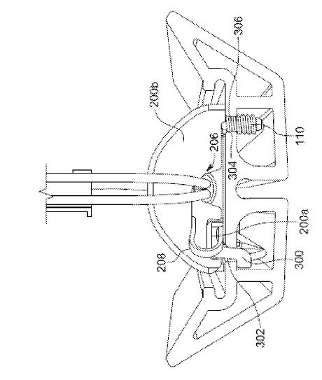
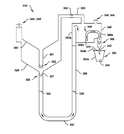
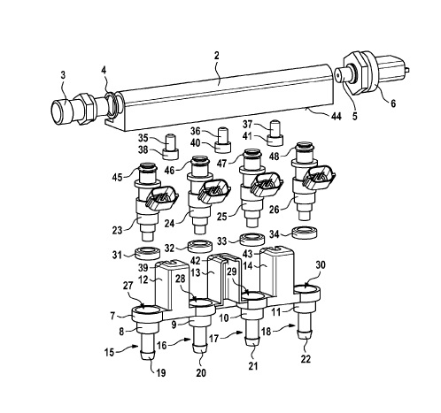
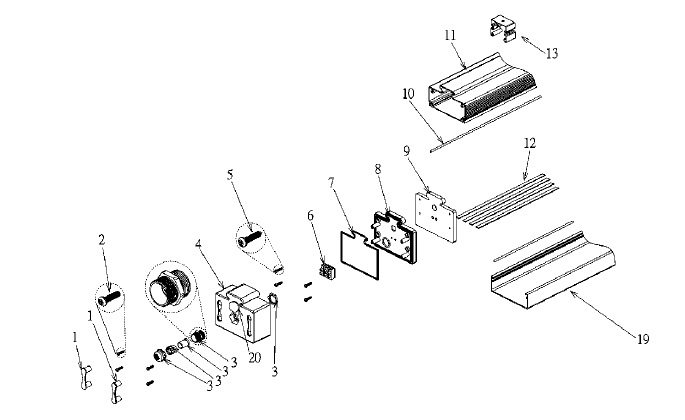
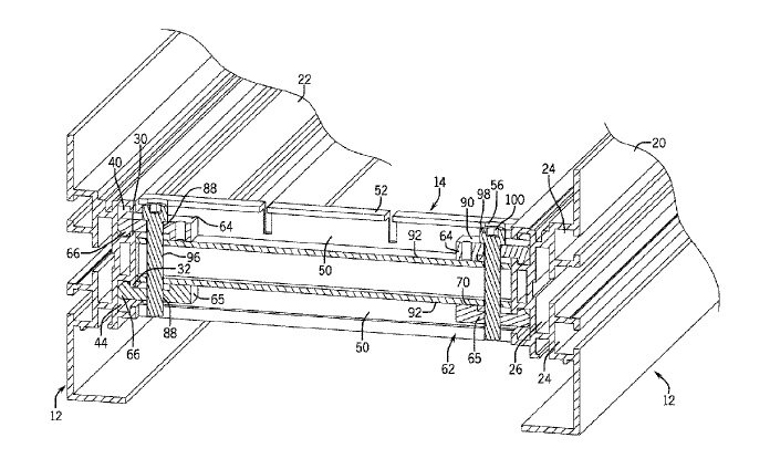
US9745938 — INJECTOR SYSTEM — Robert Bosch GMBH (Germany) — An injector system which is in particular used as an injector block for fuel injection systems of mixture-compressing, spark-ignited internal combustion engines includes a fuel distribution rail made of an aluminum extrusion profile or a soldered stainless steel part, a counter bracket, a first injector, and at least one second injector. Here, the counter bracket has a first connecting piece and a second connecting piece. The first injector is joined to the counter bracket on an input side of the first connecting piece with the aid of an elastic sealing ring. The second injector is joined to the counter bracket on an input side of the second connecting piece with the aid of an elastic sealing ring. In this case, the counter bracket is connected to the fuel distribution rail. The fuel distribution rail is used for distributing compressed natural gas to the injectors. The injector system has a compact design.
US9738318 — VEHICLE FRAME ASSEMBLY — Honda Motor Co., Ltd. (Japan) — A vehicle frame assembly includes a structural pillar defined by a first structural node, a second structural node, an upper outer member and an upper inner member spaced laterally from the upper outer member. The upper outer member extends substantially vertically between the first and second structural nodes and has first and second end portions connected to the respective first and second structural nodes. The upper inner member is angled laterally inwardly relative to the upper outer member and has a first end portion connected to the first structural node. The first and second structural nodes together with the upper outer and inner members define a first triangular load distribution path for the vehicle frame assembly which is adapted to distribute a roof crush load from the first structural node to the upper outer and inner members. The frame can be made of steel and aluminum structural components (aluminum extrusions and stampings). To prevent galvanic corrosion between the differing metals, an electrically nonconducting adhesive can be provided between the structural member and the structural node.
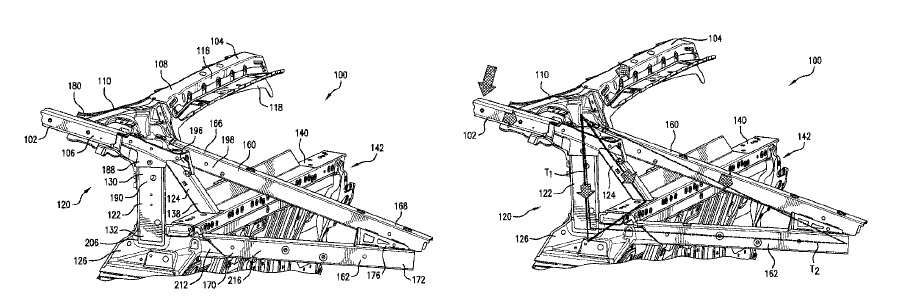
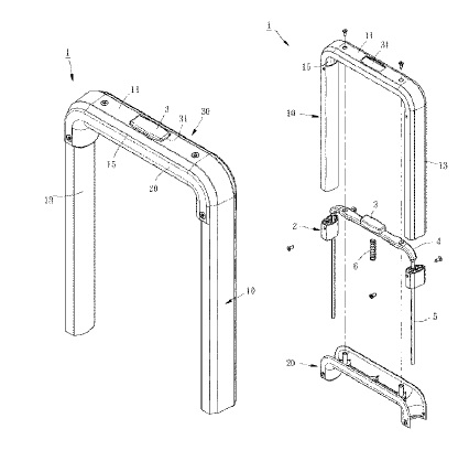
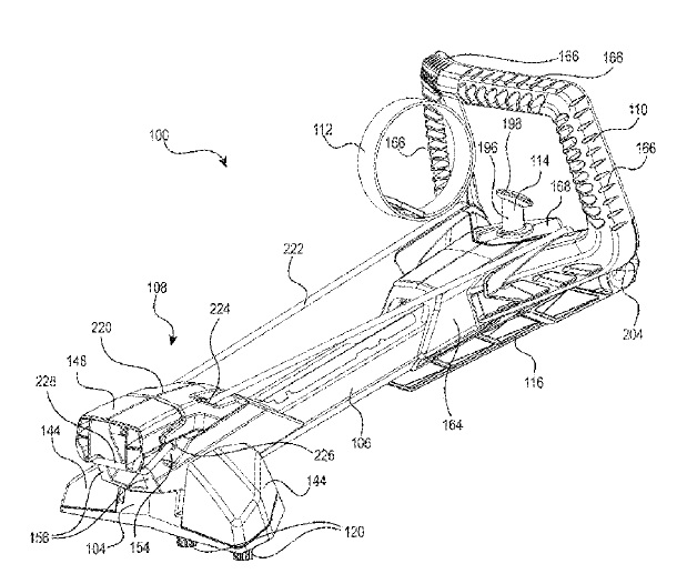
US9731797 — TOW PYLON ASSEMBLY FOR A WATERCRAFT — Bombardier Recreational Products Inc. (Canada) — A tow pylon assembly (100) for a watercraft has a pylon (106) made from an aluminum extrusion, a base connected to a lower portion of the pylon, the base being configured for connecting the tow pylon assembly to the watercraft, a bollard connected to an upper portion of the pylon, the bollard being configured for attaching a tow rope to the tow pylon assembly, and an equipment holding assembly connected to the pylon. The equipment holding assembly has a resilient member connected to the pylon. The resilient member is configured for holding equipment between the resilient member and the pylon. A personal watercraft having a rear platform and the tow pylon assembly connected to the rear platform is also disclosed.
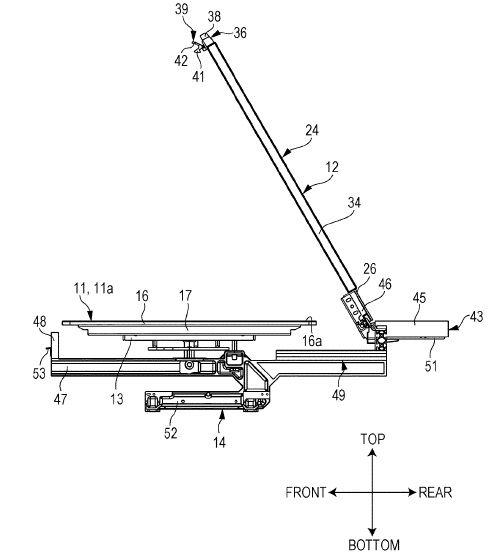
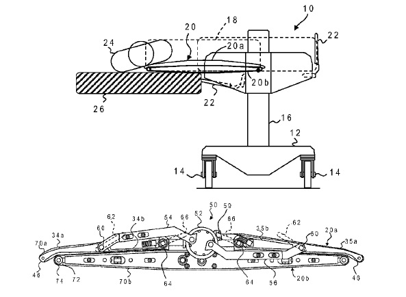
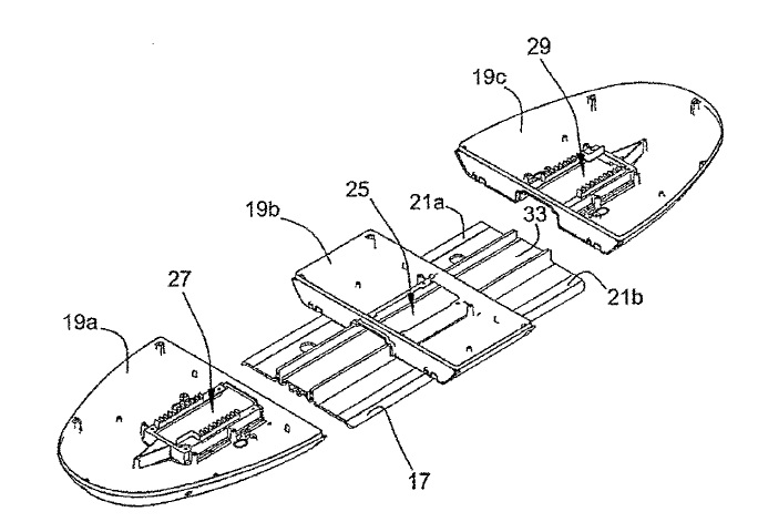
US9730849 — PATIENT LIFT AND TRANSFER DEVICE — MediGlider Corp. (USA) — A transfer device has a carriage composed of aluminum extruded elements that support drive rollers and is supported on a base, movable between a home position and an extended position. A table assembly includes a lower table fixed to the carriage and an upper table coupled to the lower table, movable between a downward position in forcible contact with the lower table and an upward position having no contact with the lower table. The table assembly moves toward the extended position with the tables in forcible contact to place the table assembly underneath the object to be transferred while keeping the base stationary. The plates are separated to lift the object on the upper table while the lower table remains resting upon the support surface. The table assembly returns to the home position while supporting the object on the upper table and keeping the upper and lower tables separated. The device may operate in a bidirectional manner.
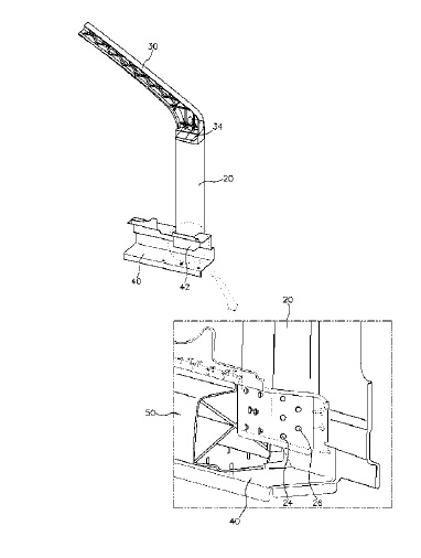
US9718500 — STRUCTURE OF HYBRID FRONT PILLAR — Hyundai Motor Company (Korea) — A structure of a hybrid front pillar of a vehicle includes a front pillar lower portion made of extruded aluminum, a side reinforcing member made of a carbon fiber reinforced plastic, and a front pillar upper portion and side connecting member made of die cast aluminum. The hybrid front pillar of the vehicle is disposed at a front side of a front door unit of a vehicle, has a lower end coupled to a side connecting member and a front pillar upper portion which is disposed at an upper side of the front pillar lower portion, and is coupled to the front pillar lower portion. The front pillar lower portion has a recessed portion formed at one side of the side connecting member such that the lower end of the front pillar lower portion is inserted into the recessed portion, and a mounting portion is formed at a lower end of the front pillar upper portion such that an upper end of the front pillar lower portion is inserted into the mounting portion, thereby significantly reducing a weight of the vehicle body, enhancing rigidity of the front pillar, and omitting reinforcing components.
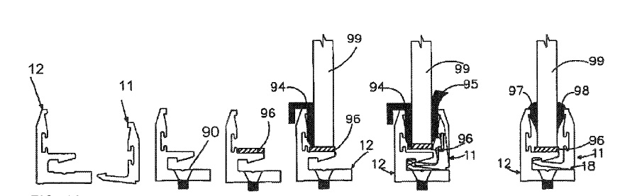
US9683402 — GLAZING SYSTEM WITH THERMAL BREAK — City Glass & Glazing (P) Ltd. (India) — The current disclosure relates to a unique and compact self-lock glazing system composed of two aluminum extrusion profiles–a male profile and a female profile–designed in such a way to self-lock glass panels using beadings, with the female profile having a first locking extension and a first leg extending therefrom, the first leg having a first tip. The system also includes a male profile having a second locking extension and a second leg extending therefrom, the second leg having a second tip that is approximately opposite the first tip, and a thermal break material positioned between the female and male profiles. When a panel is positioned between the first and second tips, the female profile and the male profile are caused to engage against the thermal break material.
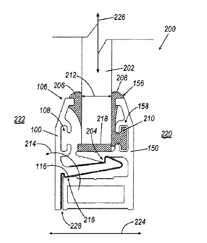
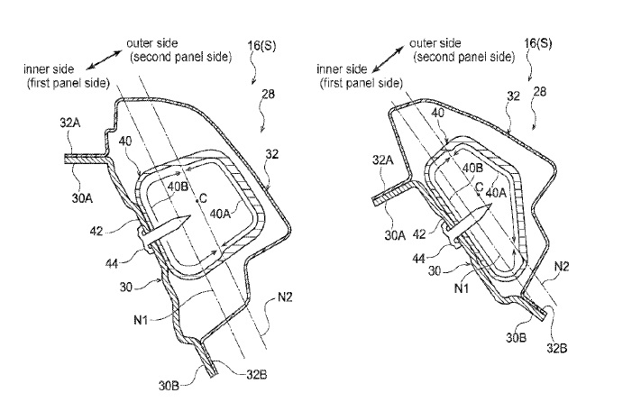
US9669877 — VEHICLE BODY FRAMEWORK STRUCTURE AND METHOD OF MANUFACTURING THE SAME — Toyota Jidosha Kabushiki Kaisha (Japan) — There is provided a vehicle body framework structure, the vehicle body framework structure including (1) a framework main body that is provided with a closed cross-sectional structure which is formed by joining together a first panel, and a second panel having less strength than the first panel, and (2) a cylindrical reinforcing member that is provided inside the framework main body and extends along the framework main body, a portion of the cylindrical reinforcing member that is located on the second panel side being formed thicker overall than a portion of the cylindrical reinforcing member that is located on the first panel side. The cylindrical reinforcing member 40 of the present embodiment is manufactured by using a hydroforming method to mold a cylindrical deviated-thickness with a deviated-thickness cross section via aluminum extrusion molding. In other words, the cylindrical deviated-thickness extruded material whose horizontal cross-sectional configuration is thicker in some portions than in others, is prepared by means of aluminum extrusion molding, and a hydroforming method is employed to mold this deviated-thickness extruded raw material into the cylindrical reinforcing member 40. Accordingly, the thicknesses of the inner panel side and the outer panel side are mutually different, and the cylindrical reinforcing member 40 whose shape conforms to that of the pillar main body 28 can be manufactured easily.
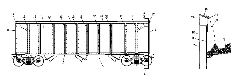
US9669845 — OPEN TOP HOPPER RAILCAR WITH LADING SHEDDING TOP CHORD AND CORNER CAP AND INTEGRATED DOOR OPERATING CONTROLS WITH MANUAL OVERRIDE — JAC Operations, Inc. (USA) — A open top railcar comprises a railcar body supported on the spaced trucks, the body comprising side and end structures on the railcar, and a top chord extending the length of the side structures and the width of the end structures, wherein the top chord includes an inwardly sloped top surface for discharging lading toward the railcar interior. The top chord 13 may be a closed section aluminum extrusion, although open section shapes are also possible but the closed section offers some structural advantages. The railcar may further include corner cap, or end cap members, including inwardly sloped lading discharging top surfaces. The railcar may be a hopper railcar having discharge chutes forming body pockets opening into the interior with pneumatic doors having manual override for each door. The railcar may include a nonmetallic touch pad housing secured to the side structures and including a plurality of touch plates mounted in the housing configured for operating selective individual doors and combination of doors.
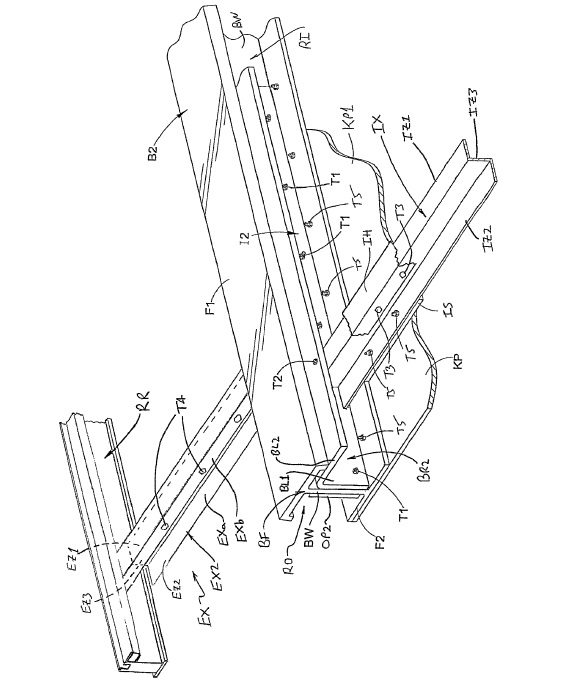
US9656701 — PLATFORM TRAILER WITH REINFORCED NECK — East Manufacturing Corporation (USA) — A platform trailer neck reinforcement structure includes a first beam reinforcement structure that includes: (i) a first beam inner insert connected to an inner side of the first beam and (ii) a first beam outer insert connected to an outer side of the first beam. The neck reinforcement structure also includes a second beam reinforcement structure that includes: (i) a second beam inner insert connected to an inner side of the second beam and (ii) a second beam outer insert connected to an outer side of the second beam. Internal cross members extend between and interconnect the first beam inner insert and the second beam inner insert. In one embodiment, the first and second beams are made from an aluminum alloy extrusion such as 6061-T6, and the first and second beam reinforcement structures are made from 304 stainless steel. A first group of external cross members are located between the first beam outer insert and the left-side rail, and a second group of external cross members are located between the second beam outer insert and the right-side rail. Each external cross member comprises an inner segment connected to an outer segment, said inner and outer segments of each external cross member of the first group connected respectively to the first beam outer insert and the left side rail, and the inner and outer segments of each external cross member of the second group connected respectively to the second beam outer insert and the right-side rail.
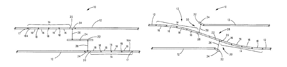
US9644325 — CROSS-OVER SWITCH FOR A MONORAIL — Bombardier Transportation GmbH (Germany) — A cross-over switch system for switching a monorail vehicle between two fixed guideway beams is provided. The cross-over switch system includes two articulated beams and a median beam. Each one of the two articulated beams, constructed of a chain of pivotably interconnected segments made of aluminum extrusions, is pivotably connected to a different one of the two parallel fixed guideways. The median beam, which is pivotable in its center, is located at a median distance between the two parallel fixed guideway beams. When in a switching mode, the median beam is pivoted and each segment of each articulated beam is also pivoted so that each one of the articulated beam abuts an opposed end of the median beam.
US9643461 — STRUCTURE FOR MOUNTING HOOK BRACKET TO BUMPER REINFORCE AND BUMPER STRUCTURE — Kobe Steel, Ltd. (Japan) — The present invention relates to a structure for mounting a hook bracket formed of an aluminum alloy extrusion to a bumper reinforce having a hollow cross-section, and further reduces the weight of the hook bracket and the weight of the mount structure without deteriorating towing performance. The hook bracket has a cut that is formed in an extrusion cross-section (a cross-section perpendicular to the direction of extrusion) and extended from the rear end of a shaft portion into the hollow in the bumper reinforce. Further, an internally threaded hole is formed. The shaft portion of the hook bracket is penetrated through a hole formed in front and rear walls of the bumper reinforce and fillet-welded to the front and rear walls. The shaft portion is not fillet-welded to the rear wall at a position where the cut is formed.

US9636984 — INTEGRATED EXTRUDED BATTERY ENCLOSURE ATTACHMENT — Ford Global Technologies, LLC (USA) — A hybrid electric vehicle includes a floor and an aluminum battery enclosure. The enclosure has L-shaped formed side walls made from an aluminum extrusion, each at least partially defining a traction battery cavity and including a foot attached to the floor. Each of the feet extends an entire length of the corresponding side wall to distribute impact energy along the entire length to maintain a relative position between the floor and enclosure.

US9625128 — HIGH POWER TRI-PROOF LED LAMP — Xiamen PVTECH Co., Ltd. (China) — A high power Tri-proof LED lamp, comprises a lower PC cover, an upper extruded aluminum cover and two end caps. Each end cap includes an inner end cap and an outer end cap. Said upper aluminum cover and lower PC cover are secured with the inner end cap by four inner end cap screws. The outer end cap is secured with the inner end cap by outer end cap screws. The tri-proof LED lamp in accordance to present invention brings more possibilities for manufacture of lamp in any length for any specific application, and to have good heat radiation efficiency and flexibility in power design, along with an extended life cycle and the convenience in installation and maintenance. With implementation of the emergency power supply module, the lamp in accordance with present invention may be able to deal with emergency situation, i.e. to work in the event of power failure. Furthermore, the end cap comprises an illumination sensor module mounted on the outer end cap, which is able to detect amount of ambient light to control the light source via the elongated printed circuit board. Also, the present invention raises the water proof and explosion proof degree to meet the requirement of the IP66 standard.
US9618182 — LIGHT-INFLUENCING ELEMENT FOR INFLUENCING THE LIGHT EMISSION OF ESSENTIALLY POINT LIGHT SOURCES — Zumtobel Lighting GMBH (Austria) — A light-influencing element for influencing the light emission of essentially LED point light sources having at least two lenses which are juxtaposed and integrally connected to each other, each having a cavity defining a light entrance section of the lens, and a light exit surface opposite the light entrance section, at least two of the lenses being designed differently with regard to their light entrance sections. The LED light fixture or luminaire 1 has an elongated profile body 2 as supporting element, which can be an aluminum extrusion profile. The profile body 2 consists of two sidewalls 3 and 4, which extend parallel to one another and which are connected to one another by a central limb 5.
US9611646 — CONNECTION MECHANISMS FOR STRUCTURAL MEMBERS AND RELATED ASSEMBLIES AND METHODS — Rapid Fabrications IP, LLC (USA) — A structural panel assembly includes first and second structural panels. Each structural panel includes: a substrate; an elongated male joint member comprising an aluminum extrusion at a first longitudinal edge portion of the substrate, with the male joint member including a latch member including a curved portion that extends the length of the substrate; and an elongated female joint member including an aluminum extrusion at a second, opposite longitudinal edge portion of the substrate, with the female joint member including a curved channel that extends the length of the substrate. The curved channel of the female joint member of the first structural panel is sized and configured to receive the latch member of the male female joint member of the second structural panel with the first and second structural panels in a coupled position.
US9617078 — CONVEYOR FRAME ASSEMBLY WITH CROSS SUPPORTS — Dorner Mfg. Corp. (USA) — The present disclosure relates to a conveyor frame assembly that includes a pair of spaced side rails formed from extruded aluminum and joined by one or more cross supports. Each of the cross supports includes an attachment clamp such that the first and second ends of the cross support can be securely attached to an inner surface of the side rails. The attachment clamp includes a pair of attachment jaws that are joined to each other by an adjustment member. Rotation of the adjustment member causes the attachment jaws to move toward each other. As the attachment jaws move toward each other, an engagement surface formed on each of the attachment jaws causes the side rails and cross support to move toward each other to securely attach the cross support between the side rails to allow for easy and convenient construction and field modification of the conveyor frame assembly.
US9611642 — EXTERIOR OPAQUE HIDDEN FRAME WALL UNIT — Advanced Building Systems, Inc. (USA) — This invention is related to the building envelope system design applicable to an exterior wall design such as a curtain wall system or a window wall system with aluminum extrusion frame members and consisting of exterior opaque hidden frame wall units and systems combining facing plates and composite insulated panels in a pressure-equalized Airloop system, permitting an opaque hidden frame wall unit without the need for intermediate stiffeners for resisting wind load, without exterior aesthetic problems associated with composite insulated panels, without a separate interior wall, and without interior condensation problems. Also provided are exterior opaque hidden frame Airloop wall units and systems with the air seal being isolated from the water seal on an offset vertical plane and away from the interior surface of the facing plate.
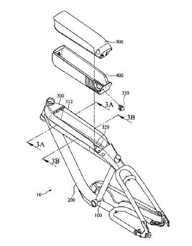
US9611003 — ELECTRIC BICYCLE FRAME — Fairly Bike Manufacturing Co., Ltd. (Taiwan) — An electric bicycle frame includes a seat tube, a down tube, a top tube made of a hydroformed aluminum tube extrusion, a battery box, and a battery body. At least a part of the top tube of the electric bicycle has continuously varying cross-sections. The seat tube includes an upper portion and a lower portion. The down tube includes a first end and a second end. The second end is connected to the lower portion. The top tube includes a third end, an expanding tube, and a fourth end. The fourth end is connected to the upper portion. The expanding tube is between the third end and fourth end. The expanding tube includes a tube diameter varying portion and a top opening. The tube diameter varying portion includes continuously varying cross-sections. The battery box is assembled inside the top opening of the expanding tube. The battery body is received in the battery box.
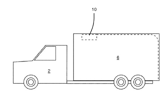
US9610830 — AUTOMATIC DOOR OPENER FOR DELIVERY TRUCKS — Lift Tech Holdings, LLC (USA) — An automatic door opener for delivery trucks may include a door opener motor, clutch, and transmission which are connected to a door opener rail which can be made from an aluminum extrusion. The automatic door opener is attached to the roof of a delivery truck cargo bay and the door opener motor is operable to open and close a cargo door. The clutch and motor are controlled by a motor control computer which may be programmed to automatically operate the clutch, close the cargo bay door, and disengage the clutch as desired. A rail carriage may be connected to the cargo bay door by a door connector arm which includes a quick release connection to the carriage and which may be operated from the outside of the cargo bay door. A sensor may be connected to the door opener rail and to the motor control computer such that the motor control computer tracks the position of the carriage along the door opener rail independent of the operation of the motor. As the rail chain 34 is moved to operate the door, the slider 46 slides along the length of the rail 30 within the aluminum extrusion and opens or closes the door.
US9598112 — FRONT PILLAR FOR A VEHICLE BODY — Honda Motor Co., Ltd. (Japan) — A vehicle frame structure includes a front pillar having an internal space defined by a forward wall, a rear wall, an outer lateral side wall, and an inner lateral side wall. An aluminum extrusion can be used for the front pillar, and in some instances part of the front pillar can be cast aluminum for frames of aluminum vehicles. The internal space is partitioned by a longitudinally extending first rib and a laterally extending second rib interconnecting the first rib and the inner side wall. The first rib separates the front pillar into an outer lateral portion and an inner lateral portion. The outer lateral portion is defined by an outer lateral section of each of the front and rear walls and the outer side wall. The inner lateral portion is defined by an inner lateral section of each of the front and rear walls and the inner side wall. The inner lateral portion of the front pillar has a length greater than a length of the outer lateral portion of the front pillar.

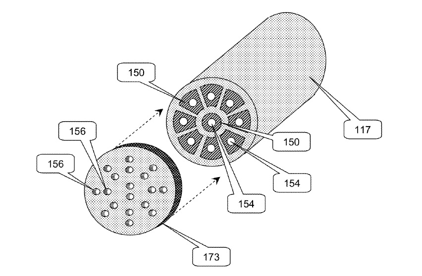
US9590409 — UNDERGROUND MODULAR HIGH-VOLTAGE DIRECT CURRENT ELECTRIC POWER TRANSMISSION SYSTEM — Alevo International, S.A. (Switzerland) — High capacity (10 GW, for example) passively cooled non-superconducting underground high voltage direct current electric power transmission lines (100) of very low loss (1% per 1,000 km, for example) and competitive cost. The transmission lines (100) include segment modules (101) linked together with compliant splice modules (102) between the segments (101), typically installed in a protective conduit (103). The segment modules (101) include relatively rigid pipe-shaped conductors (117) made of aluminum extrusions insulated by pipe-like solid insulating layers (131) to form segment modules (101) that resemble pipe. The segment modules (101) are linked together through radially and axially compliant splice modules (102) to form the transmission line (100). There are preferably wheels (300) deployed to ease insertion and removal of the assembled segment modules (101) and splice modules (102) into the conduit (103), to center each segment module (101) within the conduit (103), and/or to provide motive force and/or braking to allow the assembled segment modules (101) and splice modules (102) to be installed on a slope.
US9555569 — PLASTIC OVERMOLDING OF ALUMINUM EXTRUSIONS — Magna Exteriors Inc. (Canada) — A plastic overmold aluminum extrusion including at least one plastic overmold and aluminum extrusion, herein said plastic overmold aluminum extrusion is a transportation vehicle part selected from the group consisting of front end structures, bumper beams, cross car beams, instrument panel reinforcements, or any other component requiring improved part geometry and strength, while minimizing weight. The aluminum extrusion is formed with sufficient cross-sectional properties and features such as an internal web to help prevent undesirable collapses under injection or compression molding pressures. This improves part geometry and strength while minimizing weight. A plurality of protrusions and/or local deformations on an outer wall of the extrusion can be used to create strong mechanical interface to the plastic. Localized deformations can result from a combination of the applied plastic pressure under injection or compression molding pressures and the proximity of outer gaps of the internal web structure. A process of making the plastic overmold aluminum extrusion includes inserting at least one aluminum extrusion into a mold without mandrels and delivering plastic forming the plastic overmold.

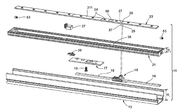
US9550453 — LIGHT BAR AND METHOD OF MAKING — Federal Signal Corporation (USA) — A light bar, which is an emergency warning system for a vehicle, is described that is of a modular construction with a frame formed from an aluminum extrusion and based on one or more large circuit boards that are populated with light beam assemblies and then fastened to an interior space of the light bar housing. Keys that automatically align the light beam assemblies on each of the boards precisely control placement of the assemblies on the board. In turn, each of the boards is keyed to the interior of the light bar housing so that when the board is fastened to the housing the light beam assemblies are automatically registered into alignment with the lenses in the housing so that the beams from the assemblies are properly oriented. The light bar is inexpensive to fabricate and can be assembled quickly and reliably, yet it provides for a high degree of customization, which is a requirement in the emergency vehicle lighting industry.
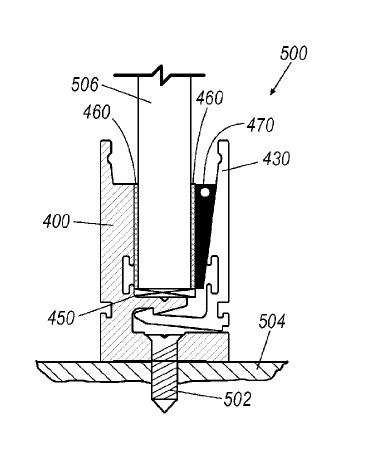
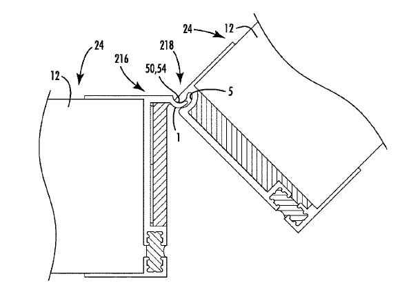
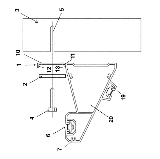
US9546757 — SUPPORT STRUCTURE FOR AN ARTICLE, METHOD OF MOUNTING THE SUPPORT STRUCTURE, AND SUPPORT BRACKET — Barco NV (Belgium) — The invention relates to a support structure for an article. In particular, the invention relates to a support structure for mounting modular articles such as display units, e.g. LED, CRT, or plasma televisions, and the like upon a wall. The support structure comprises a support bracket (1), the support bracket preferably made of an aluminum extrusion having at least one opening (15), the opening being sized to accommodate a fixing (4) by which the support bracket may be secured to a wall (3), the opening being larger than the fixing whereby the position of the support bracket (1) may be adjusted relative to the fixing (4). The support structure also comprises a support element (2), the support element having a dimension (d) which is larger than the opening (15), the support element having a fixing hole (14) therethrough, the distance between the fixing hole (14) and the periphery of the support element (2) being non-uniform. The support bracket (1) has a support surface (12) adapted for engagement by the periphery of the support element (2). The invention also provides a method of mounting the support structure, and a support bracket for use in the structure and method.
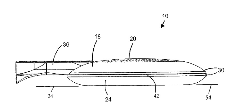
US9541246 — AERODYNAMIC LED LIGHT FIXTURE — Cree, Inc. (USA) — An LED light fixture having a light-emitting region and a perimetrical structure therearound. The light-emitting region includes at least one LED-array module supported by an LED heat sink preferably made of an aluminum extrusion open for air/water-flow and with its back base surface flat to facilitate heat transfer from the LED-array module which is flat against the back base surface. The perimetrical structure has first and second opposite substantially-aligned edge-adjacent portions each extending along the light-emitting region and meeting each other at a perimetrical edge. The first and second edge-adjacent portions converge toward each other at positions progressively closer to the perimetrical edge to form aerodynamic-drag-reducing cross-sectional profiles transverse to the fixture plane and extending in substantially all fixture-plane directions from the intersection of its two major principal axes.
US9540861 — MULTI TENSIONED COMPOSITE PROFILE — City Glass & Glazing (P) Ltd. (India) — The current disclosure relates to a unique and compact self-lock glazing system composed of two aluminum extrusion profiles–a male profile and a female profile–designed in such a way to self-lock glass panels using beadings. A self-locking support system includes a female profile having a first profile leg extending approximately orthogonally from a base, a first locking leg extending from the first profile leg, and a first tip extending from the first profile leg, wherein a gap is formed between the base and the first profile leg, and a first male profile having a fulcrum formed at an intersection of a second profile leg and a second locking leg, the second profile leg having a second tip extending therefrom. When the second locking leg is inserted into the gap, and a locking bead is positioned between the first and second tips, the first male profile is caused to rotate about the fulcrum and the first and second locking legs are caused to engage against each other.
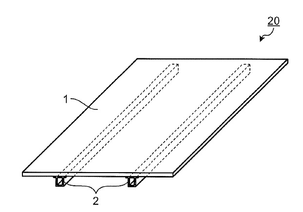
US9537443 — REINFORCING FRAME AND SOLAR BATTERY MODULE — Mitsubishi Electric Corporation (Japan) — To obtain a reinforcing frame capable of securing sufficient reinforcing strength and adhesive strength while suppressing a manufacturing cost by omitting a rim-like frame. A reinforcing frame is adhered to a rear surface, which is a non-light receiving surface of a solar battery panel, and includes a cylindrical portion that has a cylindrical shape along a longitudinal direction of the reinforcing frame and on which an adhesive surface for adhering to the solar battery panel is formed, and protruding portions that protrude from end portions along a longitudinal direction of the adhesive surface and that are substantially parallel to the adhesive surface. By using oxidation-resistant aluminum for the reinforcing rail 2, the reinforcing rail 2 can be made resistant to rust. By providing a closed section like the cylindrical portion 2a on the reinforcing rail 2, torsional rigidity can be increased.
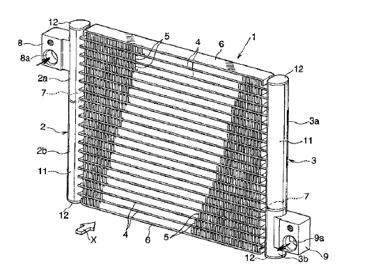
US9534851 — METHOD FOR ANTICORROSION TREATMENT OF OUTER SURFACE OF HEAT EXCHANGE TUBE MADE OF ALUMINUM EXTRUSION AND METHOD FOR PRODUCING HEAT EXCHANGER — Keihin Thermal Technology Corporation (Japan) — The anticorrosion treatment method of the invention is carried out on the outer surface of an aluminum extruded heat exchange tube which is formed of an Al alloy containing Mn 0.2 to 0.3 mass %, Cu 0.05 mass % or less, and Fe 0.2 mass % or less, and which has a wall thickness of 200 µm or less. The anticorrosion treatment method includes applying a specific dispersion of a flux powder and a Zn powder onto the outer surface of the heat exchange tube, and vaporizing a liquid component of the dispersion, to thereby deposit the Zn powder and the flux powder on the outer surface of the heat exchange tube, such that the Zn powder deposition amount, the flux powder deposition amount, and the ratio of the flux powder deposition amount to the Zn powder deposition amount are adjusted to specific values.
Editor’s Note: A portion of the patents listed here first appeared in the April 2018 issue of Light Metal Age. To read more articles and news from this issue, please subscribe.