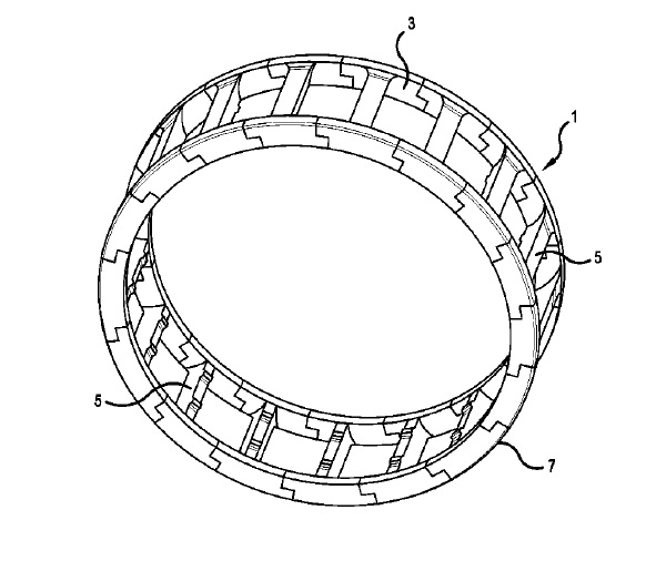
US10215234 — ROLLING BEARING CAGE OR ROLLING BEARING CAGE SEGMENT, AND METHOD FOR MANUFACTURING A ROLLING BEARING CAGE OR ROLLING BEARING CAGE SEGMENT — Aktiebolaget SKF (Sweden) — A rolling-element bearing cage or rolling-element bearing cage segment is formed from aluminum alloy AA6082 and/or AA7020 and may have a tensile strength of at least 350 MPa and/or a yield strength of at least 310 MPa and/or a hardness of at least 100 HBW. Also. a method of forming a rolling-element bearing cage or rolling-element bearing cage segment from aluminum alloy AA6082 and/or AA 7020. In an exemplary embodiment of the method for manufacturing the rolling-element bearing cage the aluminum alloy is formed into a rod, for example, extruded. A tube is then drawn from the rod. This can be referred to as manufacturing of the semi-finished product in the process. Due to the forming into a tube a strength of the material can possibly be increased. In the process the tube is subsequently subjected to the T6 heat treatment. Since the heat treatment is only performed after the forming into the tube, in some exemplary embodiments the forming itself can occur better. The tube, which can also be referred to as tube material, is subsequently dry turned and/or milled in process. In some exemplary embodiments the cage can thereby receive its geometry with a smallest-possible contamination of the tools, the workpieces, and the environment.
US10211775 — RAIL-LESS ROOF MOUNTING SYSTEM — JobDog, LLC and Imagineering Plus Plus LLC (USA) — A roof mounting system for the attachment of an article to a roof, the system comprising a plurality of PV modules each having at least one corner and a frame member, a flashing member having a top surface; an upstanding sleeve attached to the top surface of the flashing member; an elevated water seal having a borehole formed therethrough, the elevated water seal further comprising at least one screw for providing a waterproof seal between the article and the roof structure; and whereby the plurality of PV modules are interlocked in a way to provide a corner-to-corner coupling arrangement supported above the roof through the frame members of the plurality of PV modules. The roof mount wherein the additional structural member comprises an aluminum member having a top portion, a length and a groove in the top portion extending the length of the aluminum member.
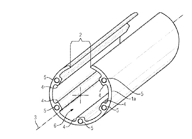
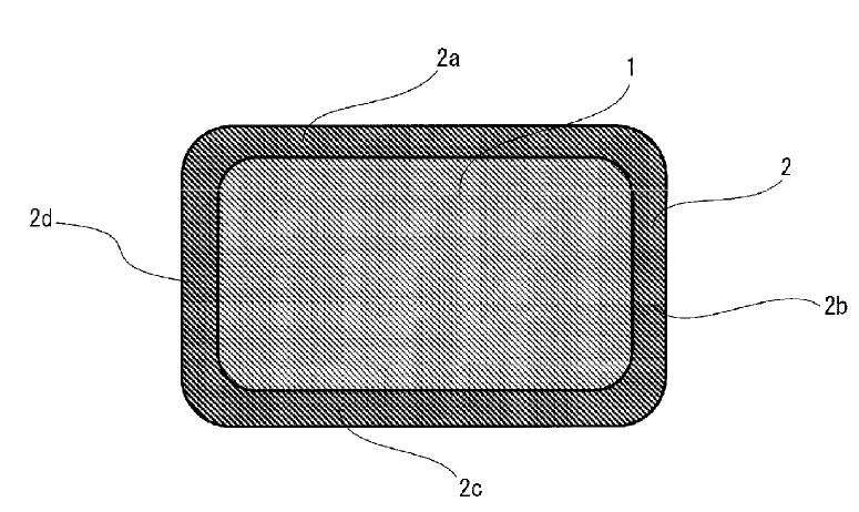
US10211617 — PHASE CONDUCTOR ARRANGEMENT — Siemens Aktiengesellschaft (Germany) — A phase conductor arrangement for an electricity transmission device has an electroconductive main member. The electroconductive main member extends along a main axis. A substantially slit-shaped opening extends along the main member. The main member is a hollow cylinder, and the opening extends along an outer wall of the hollow cylinder. The outer wall opposite the opening is closed. The phase conductor arrangement 1a in a first embodiment variant is embodied from an electrically conductive material, by way of example an aluminum alloy or a copper alloy. The peripheral surface of the base body is curved in a convex manner on the outer peripheral face, since the outer sleeve contour of the base body corresponds to a circle.
US10211506 — DUAL CAPACITIVELY COUPLED COAXIAL CABLE TO AIR MICROSTRIP TRANSITION — CommScope Technologies LLC (USA) — A transmission line transition wherein the second main body includes aluminum that couples RF energy between a coaxial cable and an air dielectric microstrip is provided. In some embodiments, the transition can combine a thin printed circuit board substrate and an insulating surface to form an effective capacitive coupling transition that can couple RF energy from the center conductor of a coaxial cable to an air microstrip. In some embodiments, the transition can include an insulating system affixed to a metallic surface, and the insulating system can secure an airstrip conductor in close proximity to an inner conductor of a coaxial cable to capacitively couple the airstrip conductor to the inner conductor of the coaxial cable. In some embodiments, the transition can employ a metallic body coated with an insulating surface to capacitively couple RF energy from the center conductor of the coaxial cable to the air microstrip. The coaxial cable to air microstrip transition in the first transition and the second transition each comprise an aluminum surface, and wherein each of the first transition and the second transition comprises an anodized insulating surface on the respective aluminum surface.
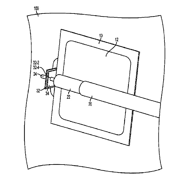
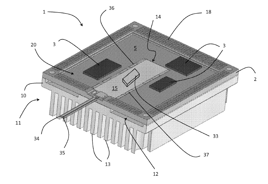
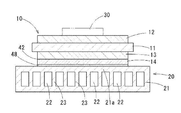
US10211121 — HEAT SINK FOR A SEMICONDUCTOR CHIP DEVICE — Elenion Technologies, LLC (USA) — A heat sink for a semiconductor chip device includes cavities in a lower surface thereof for receiving electrical components on a top surface of the semiconductor chip, and a pedestal extending through an opening in the semiconductor chip for contacting electrical components on a bottom surface of the semiconductor chip. A lid may also be provided on the bottom surface of the semiconductor chip for protecting the electrical components and for heat sinking the electrical components to an adjacent device or printed circuit board. Ideally, the heat sink 11 is comprised of a thermally and electrically conductive material, e.g., a metal, such as an aluminum alloy (167 W/m-°K) or copper (350 W/m-°K), which has a thermal conductivity greater than 150 W/m-°K. Since the heat sink 11 conducts electricity, the heat sink 11 may become an electrical ground for the components 3, and may also provide RF shielding, if the components 3 and the heat sink 11 are bonded using an electrical conductive material, such as solder or conductive epoxy such as a silver-filled epoxy.
US10211068 — POWER-MODULE SUBSTRATE WITH COOLER AND METHOD OF PRODUCING THE SAME — Mitsubishi Materials Corporation (Japan) — The present invention relates to a power-module substrate with cooler used for a semiconductor device controlling large current and high voltage and a method of producing thereof. Preventing a deformation when a metal layer made of copper or copper alloy is brazed on an aluminum-made cooler, a power-module substrate with cooler having low thermal resistance and high bonding reliability is provided: a circuit layer made of copper or copper alloy is bonded on one surface of a ceramic board and a metal layer made of copper or copper alloy is bonded on the other surface of the ceramic board; a second metal layer made of aluminum or aluminum alloy is bonded to the metal layer by solid-phase diffusion; and a cooler made of aluminum alloy is brazed on the second metal layer with Al-based Mg-included brazing material.
US10210967 — POWER CABLE — LS Cable & System Ltd. (Korea) — The present invention relates to a power cable. More particularly, the present invention relates to a power cable which is, when compared to the existing power cables, lightweight and includes a watertight layer which improves a corrosion resistance and is effectively suppressed from being peeled since the interlayer adhesiveness thereof is maintained regardless of an externally physical impact and a temperature change. The center conductor layer 10 may include a single wire formed of copper or aluminum, and preferably, copper, or a stranded wire obtained by twisting a plurality of such wires together. A standard for the center conductor layer 10, including the diameter of the center conductor layer 10, the diameter of each element wire of the stranded wire, etc., may vary according to a transmission voltage, purpose, etc. of the power cable including the center conductor layer 10, or may be appropriately selected by a technician of ordinary skill in the art. For example, when the power cable according to the present invention is an underground cable used for a purpose which requires installation performance, flexibility, etc., the center conductor layer 10 is preferably a stranded wire having higher flexibility than that of a single wire.
US10210966 — INSULATED WIRE AND COIL — Furukawa Electric Co., Ltd. and Furukawa Magnet Wire Co., Ltd. (Japan) — An insulated wire, containing: a rectangular conductor; and a thermoplastic resin layer on the rectangular conductor, wherein an adhesion strength between the thermoplastic resin layer and the rectangular conductor for a pair of sides of the rectangular conductor opposed to and an adhesion strength between the thermoplastic resin layer and the rectangular conductor for the other pair of sides of the rectangular conductor opposed to are different from each other. s the conductor used in the present invention, use may be made of any conductor that is usually used in insulated wires. The foregoing conductor is composed of an electrically conductive metal, and its material is not restricted in particular, as long as it is an electrically conductive substance. Examples thereof include aluminum or aluminum alloys, or copper or copper alloys. In a case where the rectangular conductor is composed of aluminum alloys, examples thereof include 1000-series aluminum alloys which have a low strength but a high aluminum ratio, and Al–Mg–Si-series alloys, for example, 6101 alloy of 6000-series aluminum alloys. As for the aluminum or aluminum alloys, its electric conductivity is about 2/3 of the copper or copper alloys. However, its specific gravity is about 1/3 of the copper or copper alloys. Accordingly, reduction in weight of the coil can be achieved, which allows a contribution to lightening of vehicle and improvement in fuel economy. In a case where a rectangular conductor is composed of copper or copper ally, use may be made of any conductor that is usually used in insulated wires.
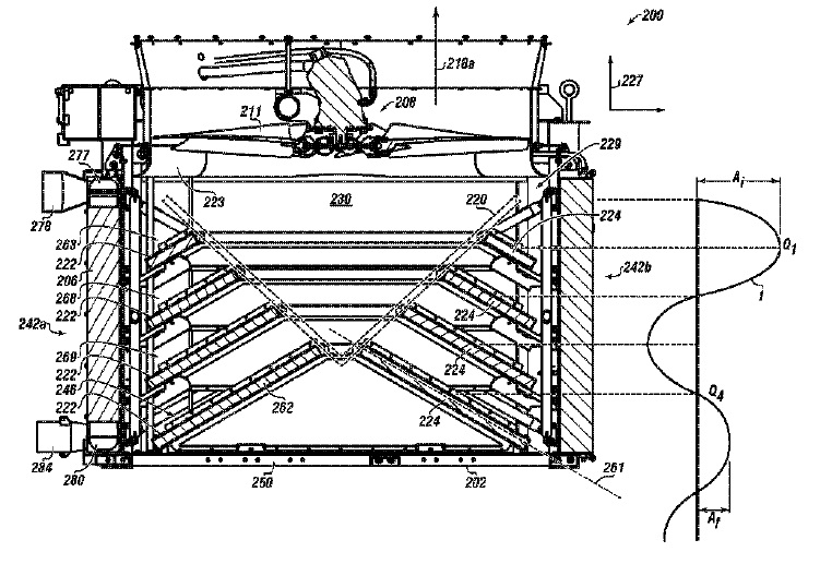
US10208983 — HEAT EXCHANGER UNIT — Global Heat Transfer, ULC (Canada) — This disclosure generally relates to a heat exchanger unit with characteristics of improved: airflow, noise reduction, cooling efficiency, and/or structural integrity. More specifically, the disclosure relates to a heat exchanger unit used in connection with equipment found in an industrial setting. In particular embodiments, the heat exchanger unit may be used for cooling various utility fluids used with a heat generating device, such as an engine, a pump, or a genset. The heat exchanger unit includes a frame and an at least one cooler coupled therewith. The heat exchanger unit has a reference axis. The heat exchanger unit includes an airflow region therein. The heat exchanger unit includes an at least one baffle coupled to the frame within the airflow region. The at least one baffle is configured at an angle to the axis. The fin elements of layers 270 a,b may be made of aluminum, or other material suitable for heat transfer, including copper, brass, steel, and composite. In aspects, the fins may be made of 3003 aluminum. Each layer 270 may have a fin density of about 4 to about 30 fins per inch. In aspects, layers 270 of the external and internal fins 273, 274 may have in the range of about 10 to about 15 fins per inch. In manufacture, the layers 270 of fins may be laid alternatingly transverse to each other between parting sheets 272 and fitted with respective header bars 275 and face bars 276. A brazing material may be placed between respective sheets 272 and bars 275, 276. The brazing material may be 4004 aluminum, or other comparable material.
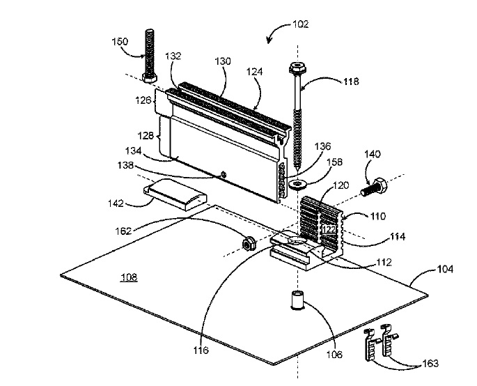
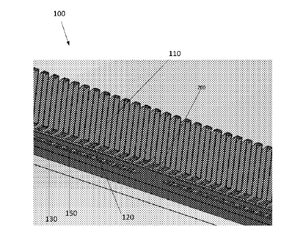
US10208940 — SYSTEMS AND METHODS FOR COUPLING A METAL CORE PCB TO A HEAT SINK — Fluence Bioengineering, Inc. (USA) — The present disclosure is related to systems and methods for coupling a metal core PCB (MCPCB) to a heat sink. More particularly, embodiments disclose a positioning a MCPCB as a based below a heat sink control dissipated heat caused by a light fixture, wherein the heat sink includes exposed fins that allow for additional air flow. As an example, it is typically ideal for greenhouses to operate with as much natural sunlight as possible. To supplement natural light from the sun, high powered lights are used within greenhouses when the sun or other natural light does not provide enough light for optimal plant growth. However, the operation of high powered lights is more costly than utilizing free sunlight and are larger in size, which blocks the incoming free sunlight and causes shading on the plants within the greenhouse. Embodiments of the disclosed invention may utilize a series of exposed fins, which increase the surface area of the heat sink creating additional air flow. As hotter air rises within the system, cooler air is drawn into the heatsink. The fins may be exposed on both sides of the longitudinal axis, allowing cooler air to be drawn towards the longitudinal axis above the heatsink and flow upward. Embodiments may include systems having side extrusions to create the plurality of fins from an aluminum block. Embodiments may include extruded aluminum to create the plurality of fins, wherein a rib is formed along the longitudinal axis of the heat sink. The extrusions and/or rib may be textured and/or contoured in the heat flow direction. This may increase the surface area of the fins and rib exposed in the heat flow direction, allowing for a more efficient system.
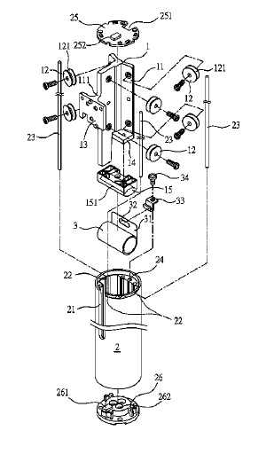
US10208793 — SLIDE MECHANISM FOR USE IN ELEVATION DEVICE — Jarllytec Co., Ltd. (Taiwan) — A slide mechanism for use in elevation device comprises: a support seat, longitudinally disposed with at least three wing pieces spaced from each other, wherein at least one lateral surface of each of the wing pieces is respectively and longitudinally pivoted with at least one roller, one of the wing pieces is extended with a neck part having a front end disposed with a connection arm; and a sleeve, having a circumference defined at the top end longitudinally formed with a rail slot, wherein an inner circumference thereof is longitudinally formed with a positioning slot at a location corresponding to the at least one rollers and allowing a guide rail to be disposed and positioned, an outer circumference of each of the rollers is formed with a guide slot sleeved in the guide rail, so that the rollers can be respectively and longitudinally slid along the corresponding guide rail. The sleeve 2 is served to allow the support seat 1 to be disposed therein, and preferably to be a tubular body formed through an aluminum alloy extrusion procedure, so that a light weight effect can be provided.
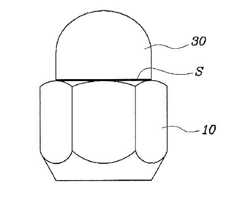
US10208783 — WHEEL NUT AND METHOD OF MANUFACTURING WHEEL NUT — Hyundai Motor Company and Kia Motors Corporation (Korea) — The present invention relates to a wheel nut, which increases corrosion resistance compared to using conventional steel materials, and to a method of manufacturing the wheel nut. Disclosed herein is a method of manufacturing a wheel nut. The method includes annealing an aluminum (Al) alloy material and preheating the annealed Al alloy material. The Al alloy material may be composed mainly of Al and may comprise chrome (Cr): ~0.18-0.28 wt %, copper (Cu): ~ 1.2-2.0 wt %, iron (Fe): ~0.5 wt % or less (but more than zero), magnesium (Mg): ~ 2.1-2.9 wt %, manganese (Mn): ~0.3 wt % or less (but more than zero), silicon (Si): ~0.4 wt % or less (but more than zero), titanium (Ti): ~0.2 wt % or less (but more than zero), zinc (Zn): ~5.1-6.1 wt % and other inevitable impurities. The annealing may be performed via treatment at about 380-420°C. for 2-5 hr and furnace cooled. The Al alloy material is also forged to form a wheel nut. Furthermore, the method includes performing an anodizing treatment to form a primary coating on the wheel nut and performing a vacuum deposition to form a secondary coating on the wheel nut. In addition, the method includes performing a surface treatment using powder paint to form a tertiary coating on the wheel nut.
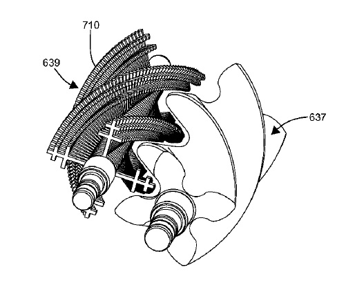
US10208656 — COMPOSITE SUPERCHARGER ROTORS AND METHODS OF CONSTRUCTION THEREOF — Eaton Intelligent Power Limited (Ireland) — A supercharger rotor with reduced rotational inertia may result in increased performance of a supercharger. The rotor may include composite material and may be extrusion molded, injection molded, or otherwise molded or laid-up. In certain embodiments, the rotor may include a core with a central portion and one or more radially extending portions. The core may be extruded or formed of stacked sheets. A molded portion of the rotor, including one or more lobes, may be molded over a corresponding one of the radially extending portions. In other embodiments, a main portion of the rotor includes one or more lobes but no central hole nor a corresponding shaft extending between ends of the main portion. Instead, stub shafts are attached to the ends of the main portion. The increased performance may include decreased noise, decreased cost, increased reliability and/or durability, increased thermal efficiency, an increased power-to-weight ratio, etc. In certain embodiments, the core includes a metallic material (e.g., aluminum, steel, titanium, etc.), and the molded portion includes a composite or a thermoplastic material (e.g., Kevlar.RTM., fiberglass, nylon, etc.). In certain embodiments, the core is substantially made of metallic material, and the molded portion is substantially made of composite material. In certain embodiments, the core is made of extruded metallic material (e.g., extruded aluminum).
US10208371 — ALUMINUM ALLOYS WITH HIGH STRENGTH AND COSMETIC APPEAL — Apple Inc. (USA) — The disclosure provides aluminum alloys having varying ranges of alloying elements and properties. In some variations, the alloy can include 3.4 to 4.9 wt % Zn, 1.3 to 2.1 wt % Mg, no greater than 0.06 wt % Cu, no greater than 0.06 wt % Zr, 0.06 to 0.08 wt % Fe, no greater than 0.05 wt % Si, and the balance is aluminum and incidental impurities. In various aspects, the Al alloys described herein can provide faster processing parameters than conventional 7xxx series Al alloys, while maintaining properties such as color, hardness, and/or strength. In some aspects, having a high extrusion productivity and low-quench sensitivity can allow for reduction in Zr grain refinement, reducing or eliminating the need for a subsequent heat treatment.
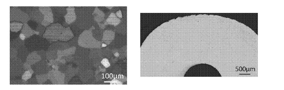
US10208370 — HIGH-STRENGTH ALUMINUM ALLOY AND MANUFACTURING METHOD THEREOF — UACJ Corporation (Japan) — An aluminum alloy contains, in mass percent, Zn: 2.5% or more and less than 5.0%, Mg: 2.2% or more and 3.0% or less, and Ti: 0.001% or more and 0.05% or less, Cu: 0.10% or less, Zr: 0.10% or less, Cr: 0.03% or less, Fe: 0.30% or less, Si: 0.30% or less, and Mn: 0.03% or less, the remainder being composed of Al and unavoidable impurities. In addition, the tensile strength is 380 MPa or more; the electrical conductivity is 38.0% IACS or more; and the metallographic structure is composed of a recrystallized structure. After being subjected to a special homogenization treatment, the ingot undergoes hot working and thereby is made into a wrought material. The temperature of the ingot at the start of hot working is set to 440°C or higher and 560°C. or lower. Furthermore, extruding, rolling, and the like can be employed as the above-mentioned hot working. After hot working has been performed, a quenching treatment is performed wherein cooling is started while the temperature of the wrought material is 400°C or higher, and the temperature of the wrought material is then cooled until it becomes 150°C or lower.
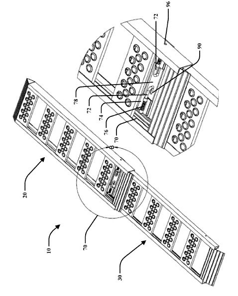
US10207881 — TELESCOPING RAMP — Horizon Global Americas Inc. (USA) — The present invention is generally related to a ramp and, more particularly, to a telescoping ramp with a locking pin system for a vehicle. A telescoping ramp may include first and second ramp sections such that the second ramp section may be received within the first ramp section and translated between an extended position and a retracted position. The telescoping ramp may include a locking mechanism that extends between at least one of pairs of rails of the first and second ramp sections. The locking mechanism may include a pair of locking pins that is selectively engageable with the first and second ramp sections. In one embodiment, the pair of locking pins may include handle portions that may be disposed between the at least one of the pairs of rails. In such embodiment, an axial movement of the handle portions along a common axis of the pair of locking pins may lock the second ramp section relative to the first ramp section. The ramp 10 components may be formed from metal, alloy or rigid polymer and in one embodiment is made from extruded aluminum material. In particular, the rails 22, 32 and rungs 24, 34 may be made with extruded aluminum that are welded together to define their respective frames. Any appropriate amount of material, such as by way of a non-limiting example, aluminum, steel, plastic or the like may be extruded to any appropriate shape. Moreover, the apertures 56 may be formed through the extrusion process or may be formed through a subsequent operation, such as by way of a non-limiting example, punching or drilling the apertures. The ramp 10 being formed from aluminum does result in the ramp 10 being lighter than use of other rigid materials, while also retaining the appropriate strength to operatively handle the loads applied during operation of the ramp 10.
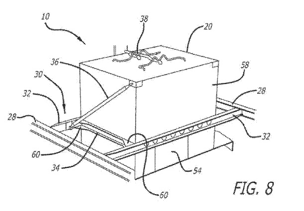
US10207806 — DROP DOWN OVERHEAD GALLEY STOWAGE SYSTEM — B/E Aerospace, Inc. (USA) — A method of installing an aircraft overhead stowage system includes installing a plurality of bin support rail fittings onto a plurality of bin support rails disposed above a ceiling of a cross-aisle galley aluminum complex; positioning a stowage compartment housing supported by a stowage support structure above the ceiling of the galley complex, the stowage compartment housing including a first stowage compartment and a second stowage compartment each movably engaged with and disposed inside the stowage compartment housing; aligning the stowage compartment housing and the stowage support structure with the bin support rails; and fastening the stowage support structure to the bin support rails using the bin support rail fittings such that the stowage compartment housing is structurally supported above the ceiling of the galley complex. the stowage support structure 30 includes “C”-shaped or “C” channel extrusions 32 intersecting with lateral channels 34 both connected to the stowage compartment housing 20, tie rods 36 (preferably 9 g tie rods) that connect the top-left and top-right corners of the front face 58 of the stowage compartment housing to the rear C-shaped extrusion, and gussets 60 further connecting the “C” channel extrusions to the lateral channels. he primary structural support framework of the stowage support structure 30 preferably includes extruded channels (32, 34), tie rods 36, formed sheet metal and machined clevis fittings 62.
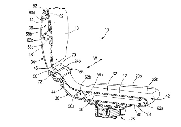
US10207776 — SEAT AND SEAT ASSEMBLY FOR USE IN A BOAT — Brunswick Corporation (USA) — A seat is designed for use in a boat and extends in a vertical height direction, a lateral width direction, and a depth direction perpendicular to the width direction. The seat includes a pan main body extending in at least the width direction and the depth and a back main body coupled to the pan main body and extending in at least the width direction and the height direction. The pan main body and/or the back main body is formed from a single extrusion having a uniform cross section in one if the height, width, and depth directions. The pan main body and/or the back main body has an open profile when viewed in the one of the height, width, and depth directions. The open profile is configured to accept and hold a further seat component therein. According to the present disclosure, at least one of the pan main body 12 and the back main body 14 is formed from a single extrusion having a uniform cross section in one of the height direction H, the width direction W, and the depth direction D. This allows the at least one of the pan main body 12 and the back main body 14 to be cut to length post-extrusion to accommodate an array of customer seating needs. Further, at least one of the pan main body 12 and the back main body 14 has an open profile 16 when viewed in the one of the height direction H, the width direction W, and the depth direction D. The open profile 16 is configured to accept and hold a further seat component therein. According to the present disclosure, at least one of the pan main body 12 and the back main body 14 is both formed from the extrusion and has the open profile 16, and the cross section of the extrusion defines the open profile 16. An extrusion that forms the pan main body 12 could have the same cross section as an extrusion that forms the back main body 14, thereby allowing the same die to be used for both bodies.
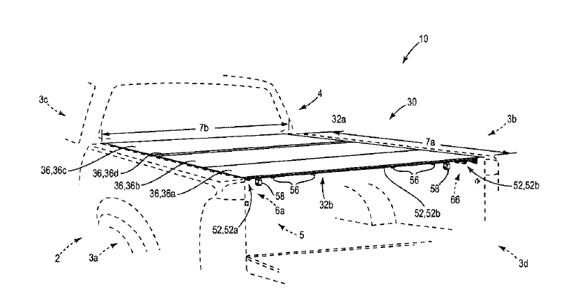
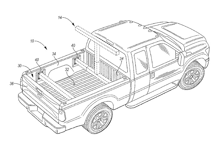
US10207623 — PORTABLE ENTERTAINMENT SUPPORT SYSTEM FOR A PICKUP TRUCK BOX — Ford Global Technologies, LLC (USA) — An entertainment support system is attached to a pickup truck having a plurality of receptacles in sidewalls of a truck box spaced above a truck bed. The entertainment support system includes a first mount having a first horizontal arm extending between opposing sidewalls of the truck box, and a vertical arm extending orthogonal to the first horizontal arm. The entertainment support system further includes a second mount including a second horizontal arm extending between the opposing sidewalls parallel to and spaced from the first horizontal arm. The forward and rear mounts 16, 18 may be formed, for example, of steel or aluminum extrusion. The forward and rear mounts 16, 18 may support components of the portable entertainment system 12, such as audio-video components. For example, the forward mount 16 may support a display device 20, such as a projector screen. The rear mount 18 may support a visual source device 22, such a video projector. The rear mount 18 may also support one or more audio devices 24, such as speakers. The components of the truck box 30, including the truck bed 32, sidewalls 34, and tailgate 36, may be made from a sheet metal material, including but not limited to, steel sheet or an aluminum alloy sheet.
US10207569 — DOOR STRUCTURE OF AUTOMOTIVE VEHICLE — Mazda Motor Corporation (Japan) — Vertical frame portions provided at both side portions of a door frame are a light-metal casting, plural connecting frames, which are made of a light-metal hollow extrusion made of an aluminum alloy or a magnesium alloy that connect the vertical frame portions, the vertical frame portions are provided with protrusion portions which engage with inward connecting frames in a longitudinal direction, plural attachment portions which attach the outward connecting frames and the vertical frame portion are provided at different points in the longitudinal direction, and an outward connecting frame is provided with an upper rib which engages with an engagement recess portion provided at an upper portion of a door outer panel formed in a non-planar shape.
US10207568 — HEATER FOR MOTOR VEHICLE — Hanon Systems (Korea) — Provided is a heater for a motor vehicle including: a heat source part: a heat source part rod including a rod sidewall and a rod cover in order to receive the heat source part; a first heat radiating plate including a first heat generation region in which one side of the heat source part is disposed and a first air movement region in which at least one or more first through-holes are formed; and a second heat radiating plate including a second heat generation region in which the other side of the heat source part is disposed and a second air movement region in which at least one or more second through-holes are formed. Particularly, the heat source part is disposed between the first and second heat radiating plates, and the rod sidewall is provided integrally with the first heat radiating plate. The rod sidewall RS configuring the heat source part rod R is extrusion-molded integrally with the first heat radiating plate 30, such that the first heat radiating plate 30 and the heat source part 10 may be assembled to each other without using an adhesive means. Preferably, the heat radiating plates 30 and 50 may be made of an aluminum alloy or the like.
US10207310 — METHOD FOR MANUFACTURING VEHICLE STRUCTURAL MEMBER — Toyoda Iron Works Co., Ltd. (Japan) — The present invention is preferably applied to manufacturing of a hollow vehicle structure member such as a vehicle bumper reinforcement, a floor brace, a tower bar, and a cross member by using a hollow extruded material. The hollow extruded material is an extruded material having a quadrilateral tubular shape and made of aluminum, an aluminum alloy, or other metals. A method for manufacturing a vehicle structure member by using a hollow extruded material that has a pair of side plates and a plurality of connecting plates connecting the side plates together and that has a quadrilateral closed section and a longitudinal shape, such that a width dimension of the vehicle structure member, which is a distance between the side plates, varies in a longitudinal direction of the vehicle structure member, the method including: an extrusion molding step of producing the hollow extruded material with the connecting plates each having a bent shape by extrusion molding; and a widening step of increasing the width dimension by increasing the distance between the side plates partially in the longitudinal direction so as to flatten the connecting plates having the bent shape.
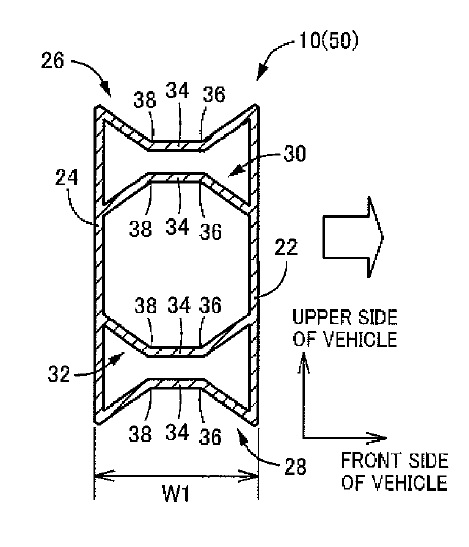
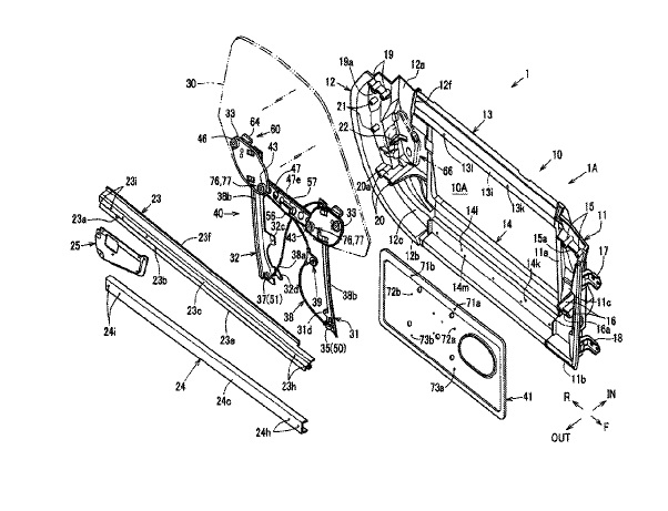
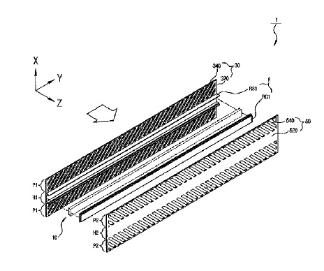
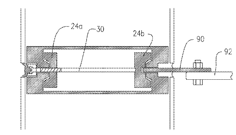
US10202762 — CONCEALED FASTENER WINDOW OR CURTAIN WALL ASSEMBLIES — New Jersey Institute of Technology (USA) — Window or curtain wall assemblies and concealed window fastening assemblies are disclosed. Each window panel includes two layers of glass or other material separated by a spacing mullion, which lines the perimeter of the window panel to create a sealed chamber. The depth of the sealed chamber between the two layers is variable to accommodate either thermal requirements, vertical and horizontal structural loads, or both. The chamber reduces heat loss due to convection allowing it to outperform current double or triple glazing window walls. Each chamber can connect through tubes to allow for air or gas transfer to enhance thermal performance and create the potential for other functional and aesthetic effects. When the window panels are assembled, the latching mechanism structurally unifies each panel to become a single monolithic surface that can also account for thermal expansion. Elements of the latching mechanism are arranged to allow the window or curtain wall to be assembled from the interior, leaving only caulking to be performed from the exterior. Concealing all of such elements helps eliminate the exposure of window mullions and minimizes maintenance of the window or curtain wall.
US10202671 — HIGH PROOF STRESS AL–ZN ALUMINUM ALLOY EXTRUSION MATERIAL SUPERIOR IN BENDABILITY — Nippon Light Metal Company, Ltd. and Honda Motor Co., Ltd. (Japan) — A high proof stress aluminum alloy extrusion material having superior bendability and crack resistance. The high proof stress aluminum alloy extrusion material is an aluminum alloy comprising: 5.0 to 7.0 wt % of zinc; 0.5 to 1.5 wt % of magnesium; 0.05 to 0.3 wt % of copper; no greater than 0.15 wt % of zirconium; 0.1 to 0.4 wt % of iron; 0.05 to 0.4 wt % of silicon; with the balance being Al and impurities, in which at least 90% of a metallographic structure is a recrystallized structure. A manufacturing method of the high proof stress aluminum alloy extrusion material includes: a step of homogenization by heating and holding a billet of the aluminum alloy at 450 to 560°C. for 1 to 16 hours and then cooling to an ambient temperature; a step of obtaining the extrusion material by heating the billet to 400 to 570°C. and extruding at an extrusion rate of 2 to 50 m/min; and a step of aging treatment by heating the extrusion material to 110 to 200oC. and holding for 4 to 24 hours.
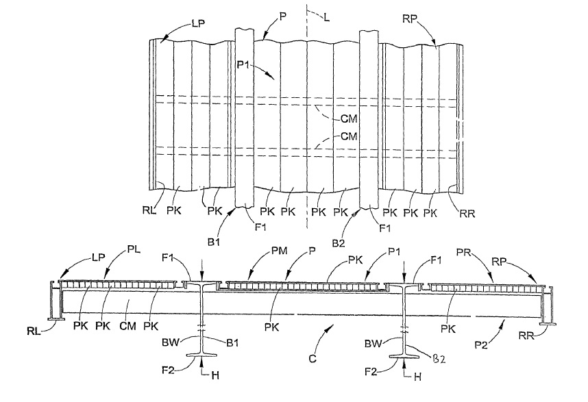
US10202153 — PLATFORM TRAILER WITH REINFORCED NECK — East Manufacturing Corporation (USA) — A trailer neck reinforcement structure includes a first beam reinforcement structure that includes: (i) a first beam inner insert connected to an inner side of the first beam; and, (ii) and a first beam outer insert connected to an outer side of the first beam. A second beam reinforcement structure includes: (i) a second beam inner insert connected to an inner side of the second beam; and, (ii) and a second beam outer insert connected to an outer side of the second beam. Internal cross members extend between the first beam inner insert and the second beam inner insert. A first group of external cross members are located between the first beam outer insert and the left side rail, and a second group of external cross members are located between the second beam outer insert and the right side rail. Each external cross member comprises an inner segment connected to an outer segment. To support the longitudinally extending platform members PK, which can be made of aluminum extrusions, the platform P further comprises a plurality of transversely extending cross members CM located beneath the platform members PK at axially spaced intervals along the entire length of the trailer. The cross members CM are welded or otherwise connected to and extend perpendicularly between the left and right side rails RL,RR, passing through the web BW of the beams B1,B2 (in some cases the cross members CM comprise three separate cross member sections or “stubs” located respectively beneath and supporting the left, middle and right platform sections and abutted with the beams B1 and/or B2 instead of a single member that passes through both of the beams B1,B2). These cross members CM can have a variety of shapes, e.g., I-beam, U-shaped, C-shaped, etc. and are defined from aluminum extrusions or the like.
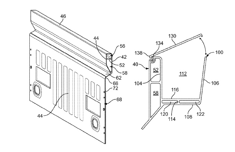
US10202152 — PICKUP BOX HEADER AND INTEGRATED TOOLBOX ASSEMBLY — Ford Global Technologies, LLC (USA) — A pickup truck box assembly may include a header, an extruded upper rail, and a toolbox. The upper rail 40, the upper rail 80, and the toolbox 100 may be formed of an aluminum alloy. The header may include a first flange extending at an angle away from a tailgate. The extruded rail may include a second flange for securing to the first flange. The toolbox is integrated with the rail and includes an extruded body having a rear wall, a forward wall, and a lower wall. The walls are arranged with one another to define a cell therebetween. A lid may be mounted to the forward wall for pivotal movement between at least a closed and an open position. Each of a pair of lateral channels may extend laterally beneath the cell and may be formed by an extrusion process with the walls. Each of a first and second truck bed side panel may be arranged with the forward and lower walls to form sidewalls of the toolbox.
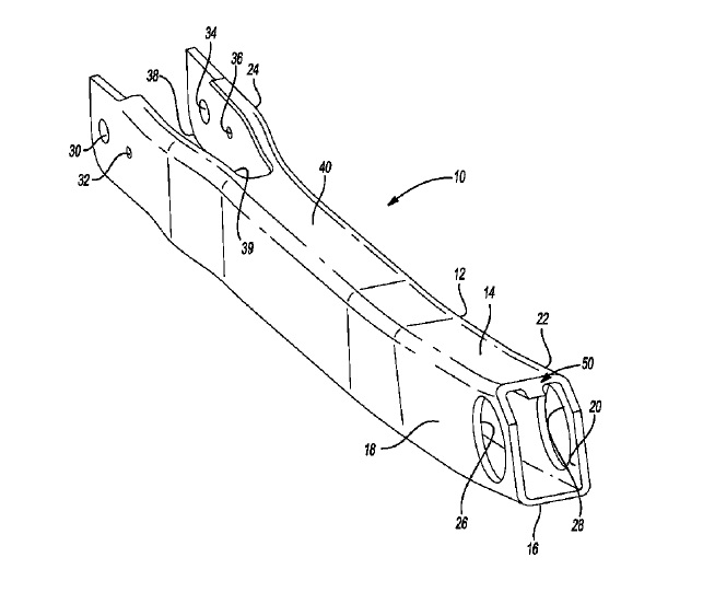
US10202013 — EXTRUDED SUSPENSION LINKAGE — Dura Operating, LLC (USA) — A suspension linkage for a motor vehicle includes an extruded body made of an aluminum or magnesium alloy having a first wall and a longitudinal length. An extruded feature is disposed on the first wall of the extruded body and extends along the longitudinal length. The extruded feature has a cross-sectional profile configured to control a flexural rigidity of the suspension linkage.
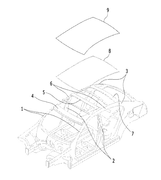
US10196092 — STRUCTURE FOR FIXING MOTOR VEHICLE ROOF MODULE — Posco (Korea) — The present invention is a structure for fixing a roof module of a vehicle, which is improved to insert and fix a polymer panel for a joining between a vehicle body structure as a steel structure and a component made of a material other than steel. The present invention provides a structure for fixing a roof module of a vehicle, comprising: a roof rail of a vehicle; a roof panel made of a material different from that of the roof rail, which is fixed at the roof rail; a polymer member coupled between the roof rail and the roof panel; and a joint member which joins the roof rail, the roof panel, and the polymer member.
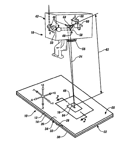
US10195689 — LASER WELDING OF OVERLAPPING METAL WORKPIECES ASSISTED BY VARYING LASER BEAM PARAMETERS — GM Global Technology Operations LLC (USA) — A method of laser welding a workpiece stack-up that includes at least two overlapping metal workpieces is disclosed, wherein among the overlapping metal workpieces of the workpiece stack-up are aluminum workpieces, and wherein at least one of the aluminum workpieces includes a surface coating comprised of a refractory oxide material. The method includes advancing a beam spot of a laser beam relative to a top surface of the workpiece stack-up and along a beam travel pattern to form a laser weld joint, which is comprised of re-solidified composite metal workpiece material, that fusion welds the metal workpieces together. And, while the beam spot is being advanced along the beam travel pattern, between a first point and a second point, which may or may not encompass the entire beam travel pattern, at least one of the following laser beam parameters is repeatedly varied: (1) the power level of the laser beam; (2) the travel speed of the laser beam; or (3) the focal position of the laser beam relative to the top surface of the workpiece stack-up.
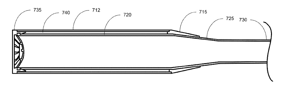
US10195504 — BASEBALL OR SOFTBALL BAT WITH MODIFIED RESTITUTION CHARACTERISTICS — Mizuno Corporation (Japan) — A softball or baseball bat with modified restitution characteristic is provided. The bat can comprise a substantially rigid core or shell made of an aluminum alloy coupled with a single or multi-piece sleeve. The core can comprise a tip end, a barrel taper, a handle taper, and a handle. The sleeve can slide over the handle portion and can be pressed, molded, or adhered to the barrel taper. The resilient sleeve can be sized and shaped such that the sleeve portion is substantially the same diameter as the tip end. The sleeve can comprise a material capable of impact absorption. The sleeve can have a composite structure with inner and outer sleeve components. The sleeve can further comprise a cone to taper the sleeve in the handle taper portion of the bat. The material and thickness of the sleeve and the core can be varied to meet applicable restitution requirements.
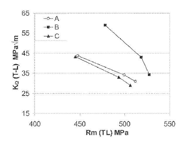
US10190200 — ALUMINUM-COPPER-LITHIUM PRODUCTS — Constellium Issoire (France) — The present invention relates to extruded, rolled and/or forged products. Also provided are methods of making such products based on aluminum alloy wherein a liquid metal bath is prepared comprising 2.0 to 3.5% by weight of Cu, 1.4 to 1.8% by weight of Li, 0.1 to 0.5% by weight of Ag, 0.1 to 1.0% by weight of Mg, 0.05 to 0.18% by weight of Zr, 0.2 to 0.6% by weight of Mn and at least one element selected from Cr, Sc, Hf and Ti, the quantity of said element selected, being 0.05 to 0.3% by weight for Cr and for Sc, 0.05 to 0.5% by weight for Hf and 0.01 to 0.15% by weight for Ti, the remainder being aluminum and inevitable impurities. he method according to the present invention makes it possible to manufacture an extruded, rolled and/or forged product. The products and methods of the present invention offer an advantageous compromise between static mechanical strength and damage tolerance and are useful in aeronautical design.
US10189340 — FOLDING TONNEAU COVER APPARATUS — Agri-Cover, Inc. (USA) — A folding tonneau cover apparatus including a cover assembly and a support frame assembly. The cover assembly having a plurality of rigid panels interconnected in series by a series of flexible hinges preferably made from a laminated woven fabric material. The rigid panels are preferably stiffened by elongated support members secured to the undersides of the respective panels and the top surfaces of portions of the rigid panels are preferably downwardly concave. The cover assembly is secured to the support frame assembly to cover a cargo box of a pickup truck by a plurality of locking members when the support frame assembly is secured to sidewalls of the cargo box. Methods of making a tonneau cover apparatus and methods of folding and unfolding the cover assembly are also disclosed.