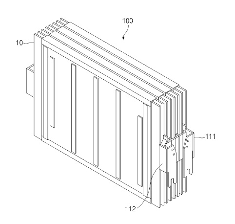
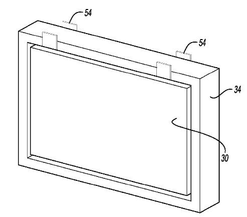
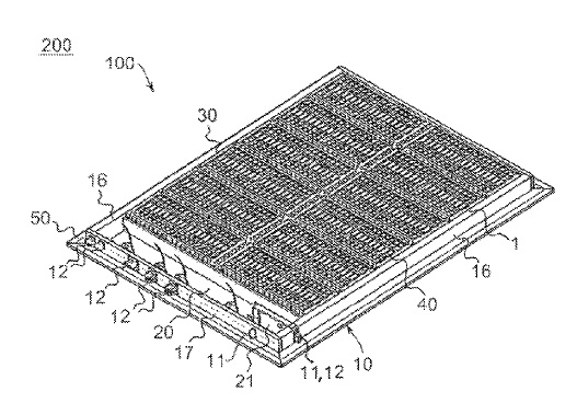
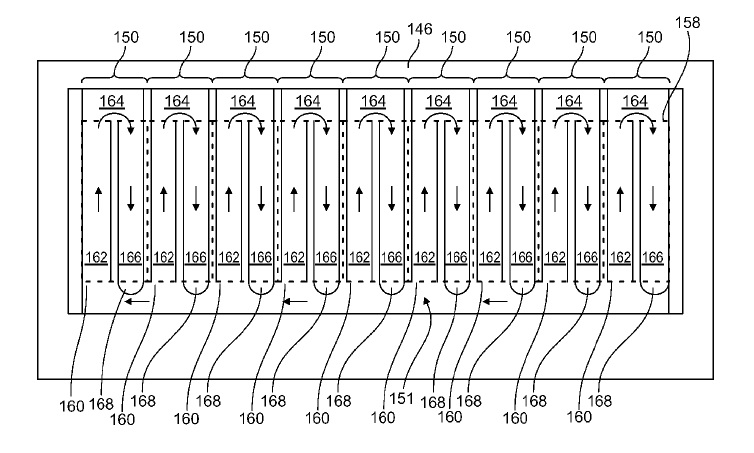
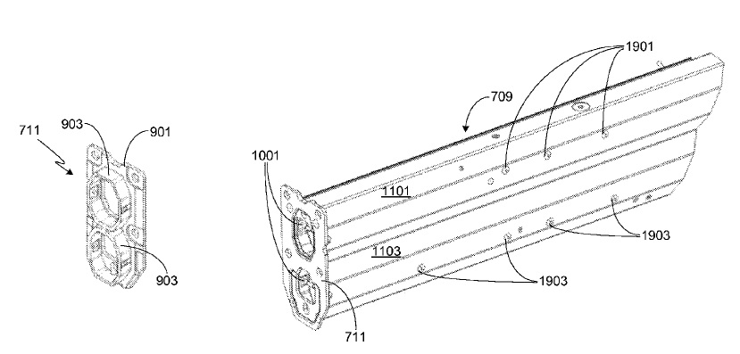
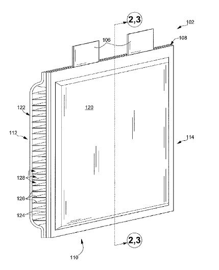
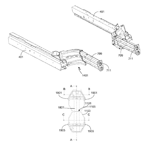
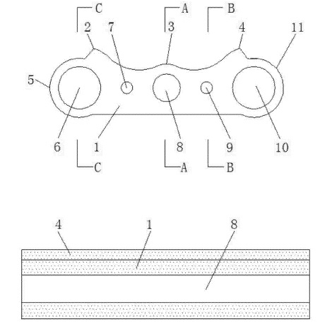
US10587020 — BATTERY PACK AND ENCAPSULATED INTERCONNECTION FOR A BATTERY PACK — Samsung SDI Co., Ltd. (Korea) — A battery pack includes a first battery module level and a second battery module level. The first battery module level includes: a first heat exchanger including a cooling tube that defines a cooling area; a first secondary battery cell in thermal contact with the first heat exchanger at the cooling area; a coolant distributor line outside the first heat exchanger and configured to supply coolant to the cooling tube; a coolant interconnector fluidly connecting the cooling tube or the coolant distributor line to the second battery module level; and an encapsulation element enclosing the coolant interconnector and confining a volume in which the coolant interconnector is arranged between the first battery module level and the second battery module level. In some embodiments, the battery pack includes a first battery module including the first heat exchange member as a rigid cooling plate. The first heat exchange member may be made of cast aluminum and may include cooling tubes made of, for example, a metal material (e.g., iron, aluminum, magnesium, or steel), through which the coolant flows. Cooling tubes of the first heat exchange member define the cooling area and are arranged such that a sufficient cooling effect is achieved near a surface of the first heat exchange member.
US10586972 — BATTERY PACK — LG Chem, Ltd. (Korea) — The present invention relates to a battery pack capable of improving stability and reducing or absorbing damage from safety issues occurring in an overcurrent state. The battery pack includes a unit cell, a bus bar electrically connected to the unit cell and short-circuited by overcurrent, and a protection part disposed in the bus bar to absorb spark occurring when the bus bar is short-circuited.
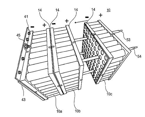
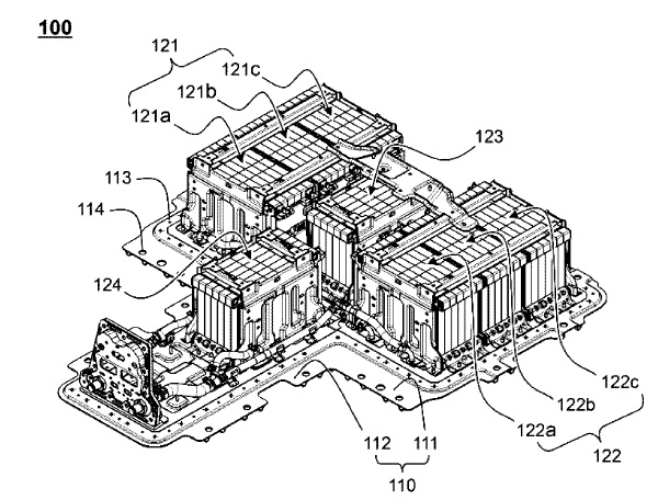
US10586959 — BATTERY BLOCK, AND METHOD FOR PRODUCING A BATTERY BLOCK — H-TECH AQ (Liechtenstein) — The present invention relates to a battery block comprising at least two battery packs and a method for manufacturing a battery block, particularly for use in electric vehicles. There is provided a battery block (10), comprising: at least two battery packs (10a, 10b, 10c, 10d, 10e), wherein each battery pack comprises at least two battery cells (11), wherein the battery cells (11) of the battery pack have electrically positive connection terminals (33) on one side and the electrically negative connection terminals (34) of the battery cells (11) are arranged on the opposite side of the battery pack, wherein a connection structure (14) is associated to each electrical connection side of a battery pack and the electrical connection terminals (33, 34) of the battery cells (11) of the battery pack each are connected to the associated connection structure (14), wherein the connection structures (14) of two neighboring battery packs (10a, 10b) that are electrically polarized in an opposite way lie against each other in order to achieve a large area connection between the battery packs (10a, 10b).
US10586952 — BATTERY MODULE COMPRISING CARTRIDGE HAVING GRIPPING PART — LG Chem Ltd. (Korea) — The present invention relates to a battery module including a cartridge having gripping parts formed on the inner surface of the frame member thereof to mount battery cells in position. A battery module having a plurality of battery cells electrically connected to each other is disclosed. The battery module includes a plurality of cartridges, each of which includes a frame member, to opposite sides of which battery cells are mounted, each of the cartridges being provided at corners thereof with fastening parts, through which adjacent cartridges are coupled to each other in order to constitute a cartridge assembly, a pair of end plates mounted to opposite side surfaces of the cartridge assembly so as to cover outermost cartridges, and a busbar assembly mounted to one surface of the cartridge assembly, the busbar assembly including busbars for electrical connection between electrode terminals of the battery cells, wherein each of the cartridges is configured such that a cooling fin, with opposite surfaces of which the battery cells are in contact for thermal conduction, is mounted to the middle part of the cartridge, when viewed in vertical section, one end of the cooling fin being exposed outward from the cartridge, and gripping parts for mounting the battery cells in position are formed on the inner surface of the frame member of the cartridge.
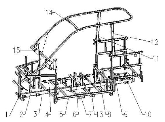
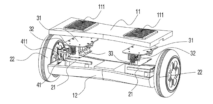
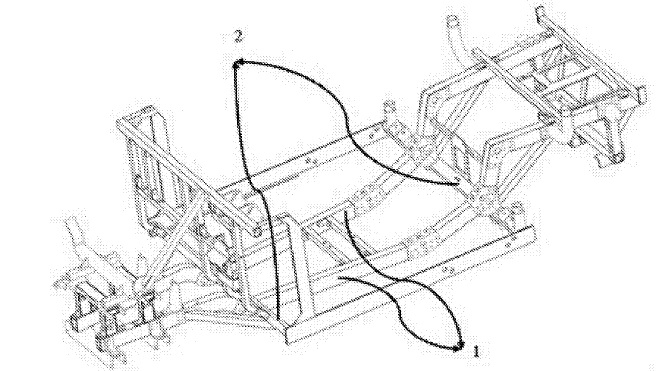
US10583886 — POSTURE VEHICLE — Shenzhen Dynamic Balance Technology Co., Ltd. (China) — The present invention relates to the technical field of electric vehicles, and provides an posture vehicle, which comprises a vehicle body, two wheelers pivoted to the vehicle body, pedals installed on the vehicle body, and two driving components installed in the vehicle body and driving the two wheelers to rotate driven by the pedals. A posture vehicle is also called as a motion sensing vehicle or an electric personal assistive mobility device. The posture vehicle has an operation principle as follows: change of an posture of a vehicle body is detected by using a gyroscope and an acceleration sensor inside the vehicle body; and a motor is accurately driven by using a servo control system to ensure balance of the vehicle body. The driving components and the wheelers are in the same operating plane. Namely, in a using process, the user treads on the wheelers, thereby eliminating interference of a balance state of the vehicle body to an output signal of the driving components and enhancing the sensitivity of the driving components for judging the balance signal. The supporting frame 630 can be made of aluminum alloy material.
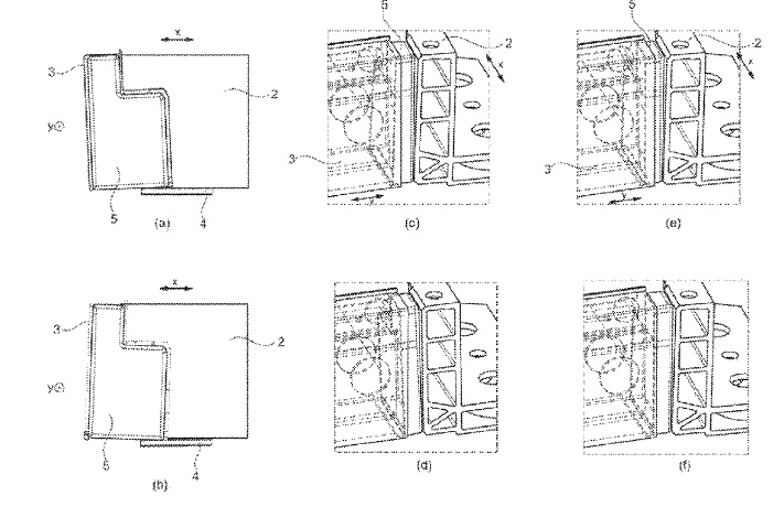
US10576836 — BATTERY CARRIER FRAME AND METHOD FOR THE PRODUCTION THEREOF — Dura Operating, LLC (USA) — In order to optimize a support frame for an electric vehicle battery in terms of tightness, compensation of component tolerances and load absorption in particular in the event of a crash, and to ensure good automated weldability, provision is made for a compensation insert to be arranged as tolerance compensation between a longitudinal profile and a transverse profile. The connection of the longitudinal profile and of the transverse profile to the compensation insert takes place preferably via a cohesive connection such as a welded joint or an adhesive bond. The compensation insert serves as a tolerance compensating bridging plug-in unit and is preferably a (die-)cast part, a deep drawn part or a forged part and is further preferably produced from a light metal alloy, in particular an aluminum alloy, and preferably as a solid material component. The longitudinal profile and transverse profile are preferably extruded profiles made of aluminum alloys. Preferably, the longitudinal profile and/or transverse profile are multi-chamber hollow profiles with one or more internal webs.
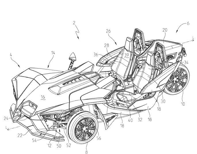
US10576817 — THREE-WHEELED VEHICLE — Polaris Industries Inc. (USA) — A vehicle includes a plurality of ground-engaging members, a frame assembly supported by the ground-engaging members, and a powertrain assembly supported by the frame. The powertrain assembly includes at least an engine. The vehicle further includes a cooling assembly fluidly coupled to at least the engine and which includes a radiator and at least one fan positioned rearward of the radiator and angled relative to the radiator. While the present disclosure is primarily directed to a three-wheeled vehicle, it should be understood that the features disclosed herein may have application to other types of vehicles such as all-terrain vehicles, utility vehicles, motorcycles, watercraft, snowmobiles, people movers, and golf carts. Additionally, such features may be applicable to hybrid vehicles, electric vehicles, and any other type of vehicle.
US10566588 — BATTERY CELL SUPPORT ASSEMBLY — Ford Global Technologies, LLC (USA) — An exemplary support assembly for a battery array includes, among other things, a frame and an insert secured to the frame. The insert is configured to hold at least one battery cell within the frame. The frame is made of a first material and the insert is made of a second material that is softer than the first material. An exemplary method of securing a battery cell within a traction battery pack of an electrified vehicle includes, among other things, compressing an insert against the at least one battery cell. The insert is secured to a frame made of a first material. The insert is made of a second material that is softer than the first material.
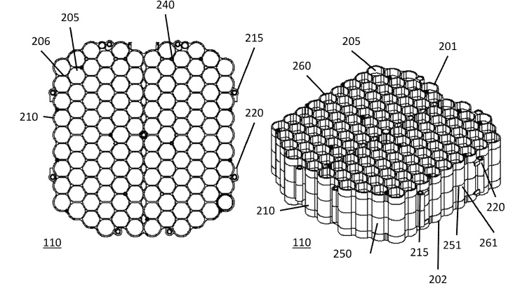
US10559797 — BATTERY ASSEMBLY HAVING A THERMAL SHIELD — Bombardier Recreational Products Inc. (Canada) — A battery assembly includes a thermal shield. The thermal shield protects battery cells in the battery assembly from hot gases vented by a neighboring cell experiencing thermal runaway. The thermal shield acts as a one-way valve, allowing the cell experiencing thermal runaway to properly vent away hot gases, but still protecting the rest of the cells in the battery pack from the hot gases. In one embodiment, a battery module frame with a hexagonal profile holds a plurality of individual battery cells in close proximity while still providing sufficient thermal isolation between the cells. The hexagonal profile of the frame advantageously creates a thin air gap between the cells, utilizing the air gap as a thermal insulator. The hexagonal profile of the frame also reduces the overall amount of material use, reducing the overall mass of the battery module frame. Finally, the hexagonal profile of the frame allows the sides of the frame to flex, compensating for variations in the outer dimensions of the battery cells.
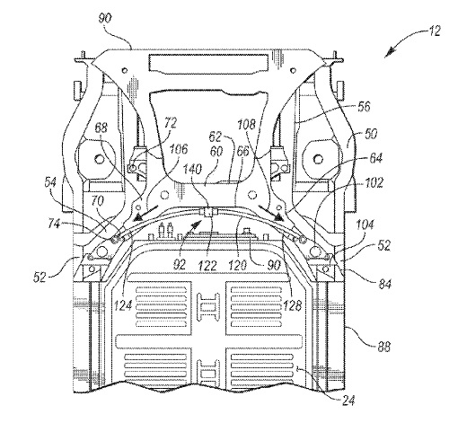
US10559795 — CHASSIS BRACE FOR PROTECTING TRACTION BATTERY — Ford Global Technologies, LLC (USA) — A vehicle includes a battery pack having siderails and includes a front cradle having rearwardly extending arms connected to the siderails and a cross member longitudinally spaced from the battery pack. A brace has a midportion connected to the cross member and ends connected to the arms such that the brace creates load paths between the cross member and the siderails to inhibit impact between the cross member and the battery pack.
US10556625 — EXTRUDED B-PILLAR REINFORCEMENT — Ford Global Technologies, LLC (USA) — Reducing the weight of a vehicle is important to meet fuel economy standards and to offset the weight of additional vehicle content required for electric vehicles and autonomous vehicles. One area where weight may be reduced is in the body structure of a vehicle, as in a B-pillar which is one part of the body structure that must withstand roof strength and side impact collision requirements. A pillar for a vehicle is disclosed that includes an outer panel, an inner panel, and an extruded reinforcement attached between the inner and outer panels. The reinforcement extends from an upper end of the inner panel to a striker attachment area on the outer panel. A lower end of the reinforcement is trimmed to be spaced from the inner panel. The inner panel may be full height of the pillar or may extend from the rocker to the striker area where the inner panel overlaps the reinforcement. The reinforcement above the striker area may function as the inner panel above the striker area. A method is disclosed for making a B-pillar for a vehicle.
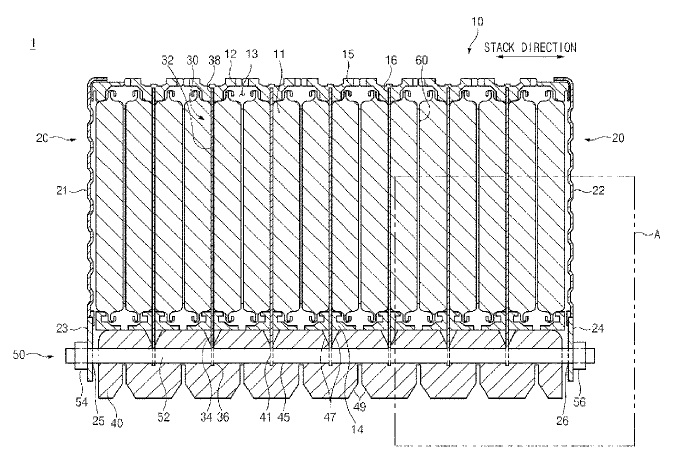
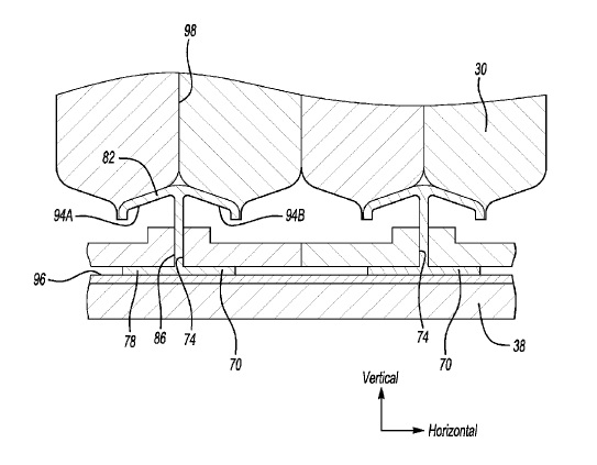
US10553919 — BATTERY MODULE WITH IMPROVED COOLING PERFORMANCE — Hyundai Motor Company and Kia Motors Corporation (Korea) — A battery module is provided. The battery module includes a battery stack that has a plurality of secondary batteries stacked on each other in multiple stages along a predetermined stack direction. Additionally, the battery module includes at least one cooling fin which has a contact part disposed to contact at least one of the secondary batteries and a fitting part that extends from the contact part to expose at least a portion of the fitting part to the exterior of the battery stack. A cooling channel which has at least one fitting groove and the fitting part is fitted into the fitting groove.
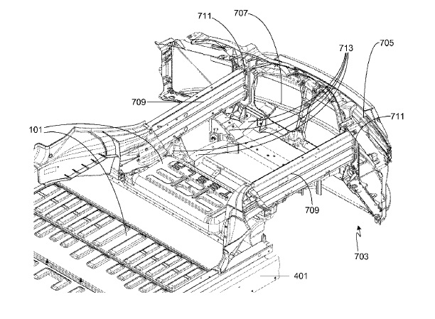
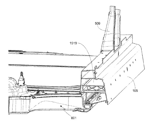
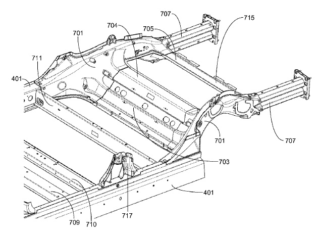
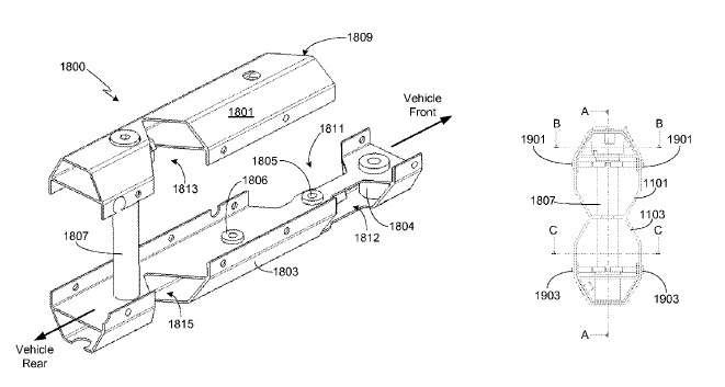
US10549620 — PROFILES IN THE FLOOR SECTION — Thunder Power Electric Vehicle Limited (China) — A mounting system for an electric vehicle includes an extruded aluminum front cross beam extending from a right side of a passenger compartment of the electric vehicle to a left side of the passenger compartment. The mounting system includes an extruded aluminum rear cross beam extending from the right side to the left side. An underside of each of the front cross beam and the rear cross beam defines a plurality of mounting features configured for mounting a battery assembly to an underside of the electric vehicle. A plurality of seat rails extends across and mounted to the front cross beam and the rear cross beam, and the plurality of seat rails are configured for mounting seats within the passenger compartment.
US10516193 — BATTERY THERMAL FIN AND METHOD OF THERMAL ENERGY TRANSFER USING A THERMAL FIN — Ford Global Technologies, LLC (USA) — An exemplary battery assembly includes, among other things, a frame, and a thermal fin extending through an aperture in the frame. The thermal fin is configured to transfer thermal energy between a battery cell and a thermal exchange plate. An exemplary method of thermal energy transfer within a battery pack includes, among other things, transferring thermal energy between at least one battery cell and a thermal exchange plate using a thermal fin that extends through an aperture in a frame.
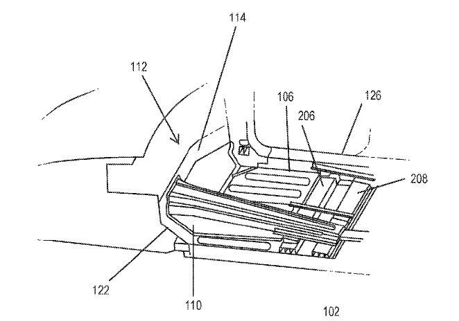
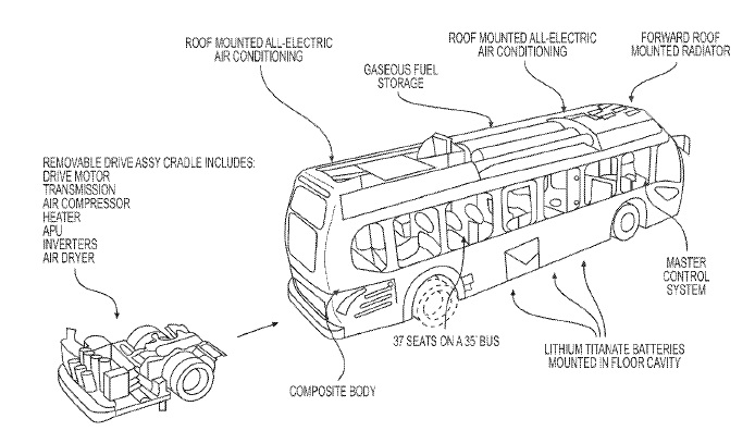
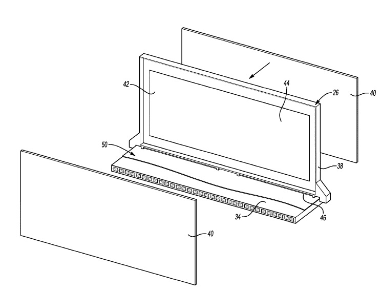
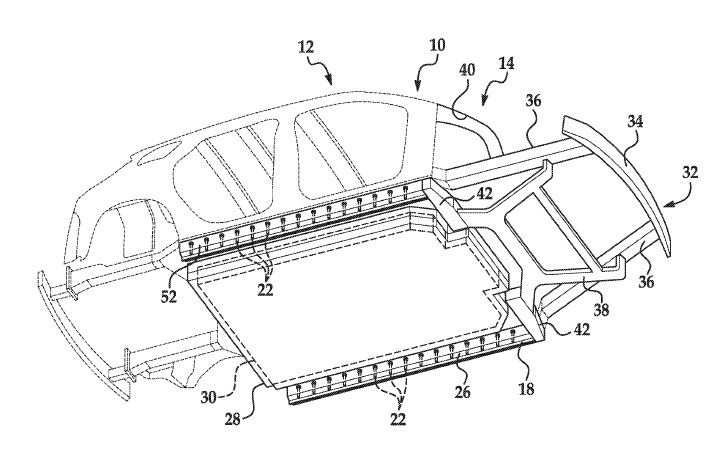
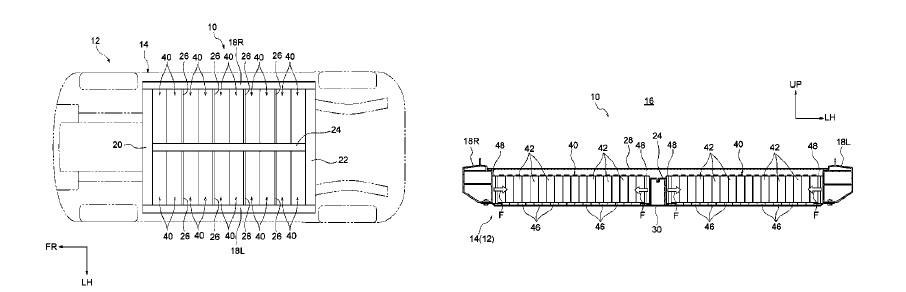
US10505164 — LOW-FLOOR ELECTRIC VEHICLE — Proterra Inc. (USA) — The invention provides for a lightweight high occupancy or heavy-duty vehicle, such as a bus, with a battery propulsion power source, which may include lithium titanate batteries. The vehicle may be all-battery or may be a hybrid and may have a composite body. Alternatively, the vehicle body may be formed of a lightweight metal or metal alloy. The vehicle battery system may be housed within the floor of the vehicle and may have different groupings and arrangements.
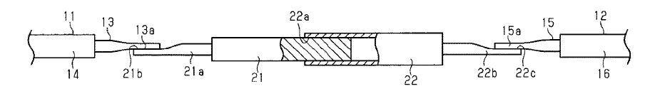
US10501029 — WIRE HARNESS — Sumitomo Wiring Systems, Ltd. (Japan) — Conventional drive motor-attached vehicles such as hybrid cars and electric vehicle include a drive motor, an inverter that is connected to the drive motor, and a high-pressure battery that supplies electric power to the inverter, wherein the inverter and the high-pressure battery are connected to each other via a wire harness including a plurality of electric wires. A wire harness that can be arranged in a vehicle, the wire harness including: a cylindrical conductor, which may be made of aluminum or an aluminum alloy, whose first end is electrically connected to a first flexible conductor that is flexible; and a tubular conductor, which may be made of aluminum or an aluminum alloy, that is electrically connected to the cylindrical conductor in a state in which a second end of the cylindrical conductor is fitted into an opening at a first end of the tubular conductor.
US10497997 — ASSEMBLY AND METHOD TO MAINTAIN CLEARANCE TO A THERMAL FIN WITHIN A BATTERY ASSEMBLY — Ford Global Technologies, LLC (USA) — An exemplary battery assembly includes, among other things, a thermal fin which is typically made of aluminum, a frame holding the thermal fin, and a stand-off of the frame configured to limit relative movement of the thermal fin toward a thermal exchange plate. A positioning method includes limiting relative movement of a thermal fin toward a thermal exchange plate using a stand-off disposed upon a battery cell assembly frame.
US10494034 — VEHICLE FRAME ASSEMBLY — Ford Global Technologies, LLC (USA) — An assembly includes a subframe, a rocker, a battery cage supported by the rocker, and a battery supported by the battery cage. The assembly includes a reinforcement bolted to the rocker and positioned to be along a load path through the subframe resulting from a vehicle frontal impact. The vehicle may include a body of unibody construction and the assembly. In the unibody construction, the body 12, e.g., the rocker 18, a second rocker 20, a front end 32, pillars (not numbered), roof rails (not numbered), etc., serves as the vehicle frame, and the body 12 is unitary, i.e., a continuous one-piece unit. The body 12 and/or the frame may be formed of any suitable material, for example, steel, aluminum, etc. The rocker 18, 20 may have a hollow cross section or the cross section may be solid. The rocker 18, 20 may be formed of any suitable material, for example, steel, aluminum, etc. The vehicle 10 may include the battery of any suitable type for vehicular electrification, for example, lithium-ion batteries, nickel-metal hydride batteries, lead-acid batteries, or ultracapacitors, as used in, for example, plug-in hybrid electric vehicles (PHEVs), hybrid electric vehicles (HEVs), or battery electric vehicles (BEVs).
US10486516 — BATTERY MOUNTING STRUCTURE — Toyota Jidosha Kabushiki Kaisha (Japan) — A battery mounting structure for an electric vehicle, the battery mounting structure includes: a plurality of vehicle body frame members that is arrayed in a vehicle width direction of the vehicle and is part of a lower frame of a vehicle body; and a plurality of cell stacks that each include a plurality of single cells. Each of the cell stacks is configured to be restrained onto the vehicle body. The left and right rockers, the front cross member, and the rear cross member are manufactured by extrusion of light metal, such as aluminum alloy. The center tunnel and the intermediate cross members as well as the floorpan and bottom plate are manufactured by press working of a plate material made of light metal, such as aluminum alloy and have a plate shape with a plate thickness direction oriented in the vehicle-height direction.
US10483705 — ELECTRICAL CONNECTOR AND ELECTRICAL CONNECTION ASSEMBLY — Tyco Electronics (Shanghai) Co., Ltd. and Tyco Electronics Technology (SIP) Ltd. (China) — The present disclosure provides an aluminum electrical connector and an electrical connection assembly for electric vehicles. The electrical connector has a first connector, a second connector, and a retainer. The first connector has a first connecting portion and a first protruding end portion that are integrally connected with each other. The second connector has a second connecting portion and a second protruding end portion that are integrally connected with each other. The second connector and the first connector are independently formed elements, respectively. The retainer is integrally interconnected with the first connector and the second connector. The second connecting portion is electrically connected with the first connecting portion. The first protruding end portion is arranged to protrude from the retainer to electrically connect a first mating connector. The second protruding end portion is arranged to protrude from the retainer to electrically connect a second mating connector. The electrical connector of the present disclosure as a modularized assembly may be applied to a plurality of scenarios and thus has extremely high universal flexibility.
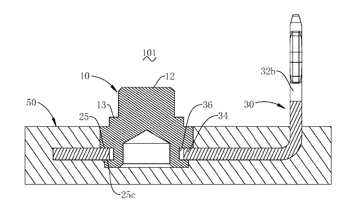
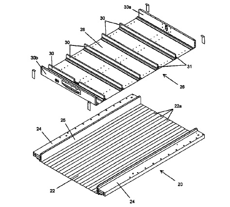
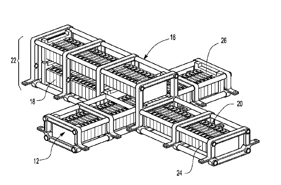
US10483510 — POLARIZED BATTERY TRAY FOR A VEHICLE — Shape Corp. (USA) — A battery tray for a vehicle includes two tray components or pieces that attach or mate together, such as with one tray component over or within the other tray component, to form sealed and separate battery containment areas. The lower tray component that has a panel portion and a pair of elongated reinforcement members integrally protruding upward from opposing edges of the panel portion. Also, the upper tray component has a panel portion and a cross members that integrally extend across its panel portion. The upper tray component is disposed at an upper surface of the panel portion of the lower tray component with the cross members extending between the elongated reinforcement members and defining a battery containment area between each of the cross members. The tray components may be separately pultruded or extruded to each have a substantially constant cross-section along the length of the respective elongated reinforcement members and cross members.
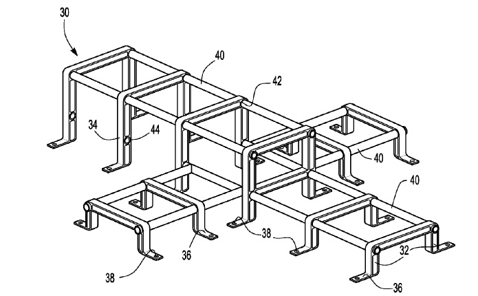
US10276848 — PROTECTIVE VEHICLE BATTERY CAGE AND METHOD OF MAKING A BATTERY CAGE — Ford Global Technologies, LLC (USA) — Battery cells for battery electric vehicles (BEV), hybrid electric vehicles (HEV) and partial hybrid electric vehicles (PHEV) are packaged in locations that are spaced away from crash zones to minimize any risk of damage during a collision event. A cage assembly is provided to protect a battery pack in a vehicle. The cage assembly includes a top sub-assembly and a bottom sub-assembly that are secured together to protect the battery pack. Extruded U-shaped frames and base frames are connected by tubular members. A method of making a cage for a battery pack of a vehicle is provided. The method may include assembling a first plurality of spaced tubes and a plurality of spaced inverted U-shaped frames to from a first sub-assembly. The method may also include assembling a second plurality of spaced tubes and a plurality of spaced frames to form a second sub-assembly. The first sub-assembly and the second sub-assembly may be assembled to enclose the battery pack.
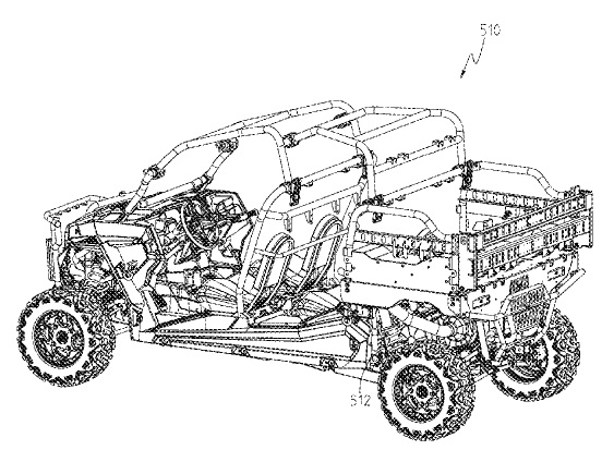
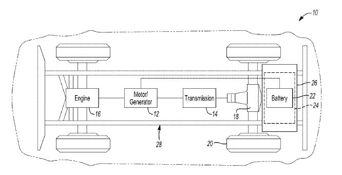
US10118477 — HYBRID UTILITY VEHICLE — Polaris Industries Inc. (USA) — A hybrid vehicle may be a series hybrid or a parallel hybrid vehicle. One embodiment of a parallel hybrid vehicle includes an engine, a transmission coupled to the engine, a front drive coupled to the transmission through a prop shaft, a rear drive coupled to the transmission, a traction motor drivingly coupled to the prop shaft, and a battery to operate the traction motor.
US10062876 — BATTERY MODULE CARRIER, BATTERY MODULE, AND VEHICLE WITH A BATTERY SYSTEM — Samsung SDI Co., Ltd. (Korea) — A battery module carrier includes a carrier frame configured to accommodate a first component carrier and a second component carrier, wherein the carrier frame comprises a plurality of longitudinal beams and a plurality of crossbeams; and wherein the first and second component carriers each comprise connection elements configured to be attached to the longitudinal beams or to the crossbeams. The first component carrier includes a control electronics assembly and a signal port, and the second component carrier is configured to accommodate a battery submodule. The carrier frame is configured to provide an external electronic connection to the first component carrier via the signal port, and each of the first component carrier and the second component carrier are configured to be individually attached and detached from the carrier frame. The second component carrier may include an integrated second coolant duct. The first and second component carriers have U-shaped, L-shaped, or T-shaped profiles.
US10396411 — TRACTION BATTERY THERMAL PLATE WITH TRANSVERSE CHANNEL CONFIGURATION — Ford Global Technologies, LLC (USA) — Vehicles such as battery-electric vehicles (BEVs), plug-in hybrid-electric vehicles (PHEVs) or full hybrid-electric vehicles (FHEVs) contain a traction battery, such as a high voltage (HV) battery, to act as a propulsion source for the vehicle. A traction battery assembly for a vehicle is provided. The traction battery assembly may include a battery cell array having a plurality of battery cells. A thermal plate may be positioned beneath the battery cells and be configured for thermal communication therewith. The thermal plate may define a plurality of channel configurations within the thermal plate. Each of the channel configurations may correspond to one of the battery cells and include an inlet and outlet on a same side portion of the thermal plate. An inlet plenum may be in communication with the inlets and an outlet plenum may be in communication with the outlets. The channel configurations and plenums may be arranged such that fluid exiting the inlet plenum enters the channel configurations via the outlets and fluid exiting the outlets enters the outlet plenum and not into the inlet of another one of the channel configurations.
US10351176 — VEHICLE BODY STRUCTURE FOR ABSORBING SIDE IMPACTS — Honda Motor Co., Ltd. — A vehicle body structure for absorbing side impacts includes a pipe member extending laterally from a first lateral side of a vehicle frame to a second lateral side of the vehicle frame. The vehicle body structure also includes a lower stamped member or assembly and an upper stamped member. The lower stamped member or assembly is disposed on an underside of the pipe member and extends laterally from the first lateral side of the vehicle to the second lateral side of the vehicle. The upper side stamped member is disposed over the pipe member to sandwich the pipe member between the lower side and the upper side stamped members. The upper side stamped member extends laterally from the first lateral side of the vehicle frame to the second lateral side of the vehicle frame.
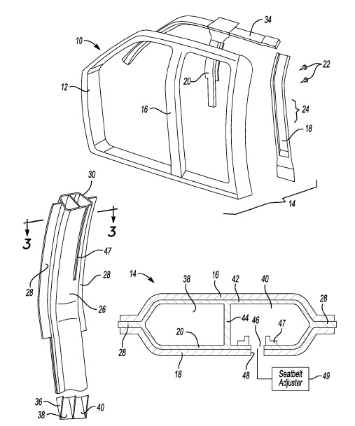
US9884642 — VEHICLE ROOF FRAME ARCHITECTURE — Ford Global Technologies, LLC (USA) — This disclosure relates to vehicle roofs, pillars and window structures made of aluminum extrusions. A roof structure includes a roof support longitudinally extending over a compartment area at a lateral centerline of a vehicle. A plurality of pillars comprising the roof support and include a transverse leg extending laterally outward from the roof support to a curved section, and a vertical leg extending downward from the curved section to a vehicle beltline. Windows are assembled to openings that are defined by two pillars, the roof support and the vehicle beltline.
US9636984 — INTEGRATED EXTRUDED BATTERY ENCLOSURE ATTACHMENT — Ford Global Technologies, LLC (USA) — A vehicle includes a floor and an aluminum battery enclosure for electric vehicles. The enclosure has L-shaped formed side walls made of aluminum extrusions each at least partially defining a traction battery cavity and including a foot attached to the floor. Each of the feet extends an entire length of the corresponding side wall to distribute impact energy along the entire length to maintain a relative position between the floor and enclosure.
US9452683 — TRACTION BATTERY THERMAL PLATE WITH LONGITUDINAL CHANNEL CONFIGURATION — Ford Global Technologies, LLC (USA) — A traction battery assembly for vehicles such as battery-electric vehicles (BEVs), plug-in hybrid-electric vehicles (PHEVs) or full hybrid-electric vehicles (FHEVs) is provided. The traction battery assembly may include a battery cell array and a thermal plate configured to support the battery cell array. The thermal plate may define an inlet port, two outer channels each having a channel inlet in communication with the inlet port, at least three inner channels disposed between the outer channels, and an outlet port. The ports and channels may be arranged such that fluid traveling through any two adjacent channels flows in opposite directions and fluid, when exiting the thermal plate, empties from one or more of the inner channels into the outlet port without first entering the channel inlets.
US9312571 — TRACTION BATTERY THERMAL PLATE WITH FLEXIBLE BLADDER — Ford Global Technologies, LLC (USA) — Vehicles such as battery-electric vehicles (BEVs), plug-in hybrid-electric vehicles (PHEVs) or full hybrid-electric vehicles (FHEVs) contain a high voltage traction battery to act as a propulsion source for the vehicle. A traction battery thermal plate assembly may include a structure having edge portions defining a cavity and configured to support a battery cell array. A flexible bladder may be disposed within the cavity between the structure and array. The flexible bladder may be configured to be filled with a fluid such that the bladder contacts the array to transfer heat between the array and fluid. The assembly may include a frame sized to receive the flexible bladder and configured to support the flexible bladder. An inlet port may be in fluid communication with the flexible bladder and a pump and may be configured to deliver fluid to the flexible bladder at a pump output rate. The flexible bladder may include ribs defining channels therebetween. The channels may be configured to direct fluid flow along the at least one surface of the battery cell array.
US9236592 — PROTECTIVE VEHICLE BATTERY CAGE AND METHOD OF MAKING A BATTERY CAGE — Ford Global Technologies, LLC (USA) — This disclosure relates to a cage for attaching a battery pack to a vehicle that protects the battery pack in the event of a collision and also facilitates servicing the battery pack. A cage assembly is provided to protect a battery pack in a vehicle. The cage assembly includes a top sub-assembly and a bottom sub-assembly that are secured together to protect the battery pack. Aluminum extrusion U-shaped frames and base frames are connected by extruded tubular members or seamless aluminum tubes utilizing MIG welding or other joining techniques.
US8702161 — SYSTEM FOR ABSORBING AND DISTRIBUTING SIDE IMPACT ENERGY UTILIZING AN INTEGRATED BATTERY PACK AND SIDE SILL ASSEMBLY — Tesla Motors, Inc. (USA) — An energy absorbing and distributing side impact system made of aluminum for use with a vehicle is provided, the system utilizing a collapsible side sill along with multiple vehicle cross-members to achieve the desired level of vehicle side impact resistance, the combination of these elements absorbing and distributing the impact load throughout the vehicle structure. A battery pack enclosure that includes a plurality of cross-members that transverse the battery pack enclosure also absorb and distribute at least a portion of the load received when either the first or second side of the vehicle receives a side impact. In this configuration the battery pack enclosure is positioned between the front and rear vehicle suspension assemblies and mounted between, and mechanically coupled to, the side sill assemblies. In addition to providing rigidity, strength and impact resistance, the battery pack cross-members segregate the batteries contained within the battery pack enclosure into battery groups.
US8696051 — SYSTEM FOR ABSORBING AND DISTRIBUTING SIDE IMPACT ENERGY UTILIZING A SIDE SILL ASSEMBLY WITH A COLLAPSIBLE SILL INSERT — Tesla Motors, Inc. (USA) — An energy absorbing and distributing side impact system fabricate from an aluminum alloys for use with a vehicle is provided, the system utilizing a collapsible side sill assembly along with multiple vehicle cross-members to achieve the desired level of vehicle side impact resistance, the combination of these elements absorbing and distributing the impact load throughout the vehicle structure. The collapsible side sill assembly includes a side sill insert, the insert divided into a collapsible portion designed to absorb impact energy and a reacting portion designed to distribute the impact energy to the vehicle cross-members.
US8585131 — REAR VEHICLE TORQUE BOX — Tesla Motors, Inc. (USA) — A rear structure for a vehicle is provided, the structure including (i) a pair of single piece rear torque boxes; (ii) a pair of rocker panels mechanically coupled to the rear torque boxes; (iii) a pair of rear rails mechanically coupled to the rear torque boxes; and (iv) at least one cross-member interposed between and mechanically coupled to the rear torque boxes. Each rear rail may be comprised of a polygonal-shaped upper hollow channel and a polygonal-shaped lower hollow channel, which may be made of aluminum alloy extrusions, where the upper and lower channels share a common wall.
US8573683 — FRONT RAIL REINFORCEMENT SYSTEM — Tesla Motors, Inc. (USA) — The present invention relates generally to vehicle structures and, more particularly, to front-end vehicle structures that provide enhanced load distribution and occupant safety in the event of a crash. A front structure for a vehicle is provided, the structure including (i) a pair of front rails (i.e., front left hand rail and front right hand rail) spaced apart in a widthwise direction with each rail extending lengthwise, where one end portion of each rail is mechanically coupled to the vehicle’s bumper and the other end portion of each rail is mechanically coupled to a torque box, and where each rail is comprised of a polygonal-shaped upper hollow channel and a polygonal-shaped lower hollow channel, and where the upper and lower channels share a common wall; and (ii) a pair of rail reinforcement members, where one rail reinforcement member is mechanically mounted within each front rail, and where a plurality of features corresponding to each reinforcement member determines how the rails react to front impact loads.
US8567856 — SWEPT FRONT TORQUE BOX — Tesla Motors, Inc. (USA) — A front structure for a vehicle is provided, the structure including (i) a pair of front rails spaced apart in a widthwise direction with each rail extending lengthwise, and where each rail is comprised of a polygonal-shaped upper hollow channel and a polygonal-shaped lower hollow channel with the upper and lower channels sharing a common wall; and (ii) a pair of curvilinear torque boxes, where one curvilinear torque box is mechanically attached to the upper and lower polygonal-shaped channels of each front rail, where each curvilinear torque box is mechanically coupled to a rocker panel, where the upper polygonal-shaped channel of each front rail is in a horizontal plane located above the top surface of the corresponding rocker panel, and where the lower polygonal-shaped channel of each front rail is in a horizontal plane that is aligned with the corresponding rocker panel.

US8567855 — BUMPER MOUNTING PLATE FOR DOUBLE CHANNEL FRONT RAILS — Tesla Motors, Inc. (USA) — The present invention relates generally to vehicle structures and, more particularly, to front-end vehicle structures that provide enhanced load distribution and occupant safety in the event of a crash. A front structure for a vehicle is provided, the structure including (i) a pair of front rails (i.e., front left hand rail and front right hand rail) spaced apart in a widthwise direction with each rail extending lengthwise, and where each rail is comprised of a polygonal-shaped upper hollow channel and a polygonal-shaped lower hollow channel with the upper and lower channels sharing a common wall; and (ii) a pair of bumper mounting plates, where one bumper mounting plate is interposed between the end portion of each channel of each rail and the vehicle’s bumper, and where each bumper mounting plate aligns the upper rail channels with the vehicle’s bumper while transferring impact loads to both the upper and lower rail channels.
US8567849 — DUAL LOAD PATH DESIGN FOR A VEHICLE — Tesla Motors, Inc. (USA) — The present invention relates generally to vehicle structures and, more particularly, to front-end vehicle structures that provide enhanced load distribution and occupant safety in the event of a crash. A system for absorbing and distributing front impact forces in a vehicle is provided, the system including a primary impact system and a secondary impact system, each of which includes a bumper and a structure for transferring impact loads. The primary impact system includes a primary bumper and a pair of front rails spaced apart in a widthwise direction with each rail extending lengthwise, where one end portion of each rail is mechanically coupled to the vehicle’s bumper and the other end portion of each rail is mechanically coupled to a torque box. The secondary impact system includes a secondary bumper and an assembly of sub-frame components separate from the front rails that allow impact loads to be transferred in parallel through the front rails and the sub-frame.

US8435668 — PRISMATIC BATTERY CELL WITH INTEGRATED COOLING PASSAGES AND ASSEMBLY FRAME — GM Global Technology Operations LLC (USA) — A battery cell assembly includes a main body configured to generate power from an electrochemical reaction. The main body has a first end and a second end, a first side and a second side, and a first major surface and a second major surface, with webs that may be formed from thin wall aluminum extrusions. A pair of electrical tabs extends outwardly at the first end of the main body. An insulating element is disposed adjacent the first major surface of the main body. A cooling element is disposed adjacent the second major surface of the main body. The cooling element includes at least one cooling passage. The at least one cooling passage is in heat exchange relationship with the main body and configured to transfer heat generated during the electrochemical reaction away from the main body.
US8424960 — FRONT RAIL CONFIGURATION FOR THE FRONT STRUCTURE OF A VEHICLE — Tesla Motors, Inc. (USA) — A front structure for a vehicle is provided that includes a pair of front rails (i.e., front left hand rail and front right hand rail) spaced apart in a widthwise direction with each rail extending lengthwise and mechanically coupled to the vehicle’s bumper and a torque box, wherein said front left hand rail and said front right hand rail are each comprised of an aluminum extrusion. Each front rail is comprised of a polygonal-shaped upper hollow channel and a polygonal-shaped lower hollow channel, where the upper and lower channels share a common wall.
CN209524313 (U) — ALUMINUM PROFILE WITH HIGH WEAR RESISTANCE FOR ELECTRIC VEHICLE — Zhejiang Joe Noble Aluminum Co. Ltd. (China) — The utility model discloses an aluminum profile with high abrasion resistance for an electric vehicle. The aluminum profile comprises an aluminum profile body and a first side connecting surface, a first protruding block is arranged on the upper portion of the aluminum material body. A clamping block is arranged on the right side of the first protruding block. A second protruding block is fixed to the right side of the clamping block. The first side connecting surface is arranged at the left end of the aluminum material body; a second side connecting surface is arranged at the right end of the aluminum material body; a first fixing hole is formed in the right side of the first side connecting surface; a first threading hole is formed in the right side of the first fixing hole, an adjusting hole channel is formed in the right side of the first threading hole, a second threading hole is formed in the right side of the adjusting hole channel, a second fixing hole is formed in the right side of the second threading hole, and a third fixing hole is formed in the rear side of the first fixing hole. The high-abrasion-resistance aluminum profile for the electric vehicle is convenient to install and use, circuits can be protected conveniently, and the whole high-abrasion-resistance aluminum profile is light and good in abrasion resistance.
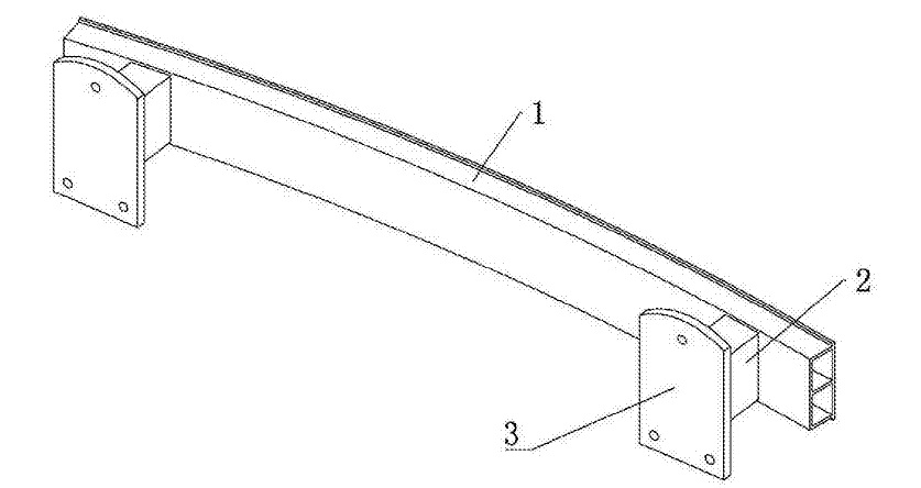
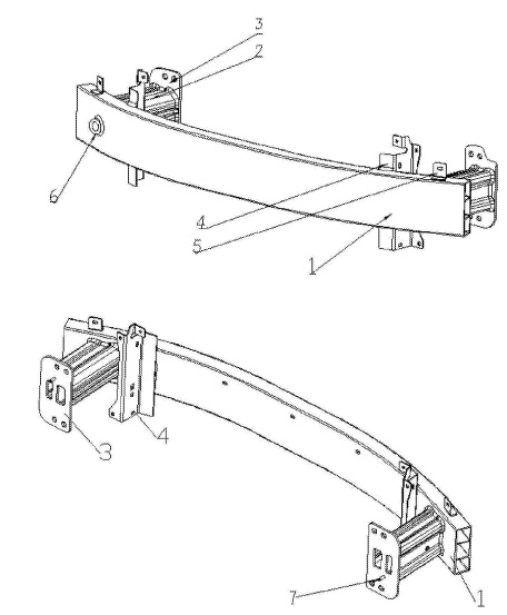
CN209395753 (U) — FRONT ANTI-COLLISION BEAM FOR SMALL ELECTRIC VEHICLE — Zhejiang Hozon New Energy Automobile Co. Ltd. (China) — The utility model relates to a front anti-collision beam for a small electric automobile. The device comprises a beam, an energy absorption box and a fixing plate, the energy absorption boxes are arranged on the rear end face of the beam and symmetrically distributed at the left and right ends of the beam. The fixed plate is arranged at the rear end of the energy absorption box; the cross beam and the energy absorption box are integrally formed by aluminum alloy respectively; at least two first through holes are formed in the cross beam in the length direction of the cross beam, the cross section of the cross beam comprises at least two rectangular sections arranged up and down, at least two second through holes are formed in the energy absorption box in the length direction of the energy absorption box, and the projection of the cross section of the energy absorption box on the fixing plate comprises at least two rectangular sections arranged up and down or left and right. According to the aluminum alloy front anti-collision beam assembly, through structural optimization, the weight of the optimized aluminum alloy front anti-collision beam assembly is reduced by about 40%; the aluminum alloy front anti-collision beam has better energy absorption performance, and the overall performance is higher than that of a traditional steel anti-collision beam; the aluminum profile forming process is simple, the cost is equivalent to that of a traditional steel anti-collision beam, and the recyclable value is high.
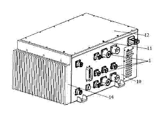
CN209454681 (U) — ALL-IN-ONE HIGH-VOLTAGE DISTRIBUTION BOX OF ELECTRIC AUTOMOBILE — Kunming Carriage Mfg. Co. Ltd. (China) — The utility model discloses an all-in-one high-voltage distribution box of an electric automobile, and aims to provide the all-in-one high-voltage distribution box of the electric automobile, which is good in protection performance. The power distribution box comprises a box body provided with a plurality of plug connectors, and an element mounting plate, a high-voltage contactor, a copper bar, afuse, a PCB adapter plate, a BMS mainboard, a shunt and a charger module which are arranged in the box body, wherein the box body comprises a rectangular shell with an open upper end, a cover plate mounted at the upper end of the shell through screws, and a sealing ring positioned between the upper end of the shell and the cover plate; an aluminum extrusion type cooling fin is arranged on the outer wall of one side of the shell. The utility model is suitable for various electric vehicles.
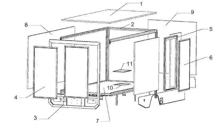
CN209305702 (U) — CARGO COMPARTMENT ASSEMBLY STRUCTURE — Zhejiang Plante Electric Vehicle Co. Ltd. (China) — The utility model discloses a cargo compartment assembly structure. Wherein the bottom plate assembly is composed of a bottom side carriage plate and a supporting steel frame, the carriage plates are connected through a frame, and the carriage plates are arranged on the left side, the right side, the top side and the front side. The frame comprises a plurality of transverse and vertical splicing strips made of extruded aluminum alloy sections with U-shaped clamping grooves formed in the splicing strips, the compartment plates are clamped in the U-shaped clamping grooves and riveted to the splicing strips, and the lower ends of the vertical splicing strips in the frame are connected to the bottom plate assembly. The splicing strips comprise a single-clamping-groove splicing strip with a single U-shaped clamping groove and a double-clamping-groove splicing strip with two U-shaped clamping grooves, and a falling positioning structure is further arranged on the cargo compartment. According to the cargo compartment, the compartment plates of the cargo compartment are spliced through the splicing strips provided with the U-shaped clamping grooves, during assembly, the splicing strips can be installed on the compartment plates firstly, then the compartment plates are spliced, modular, intensive and batched production and assembly of the cargo compartment can be achieved, and accurate positioning of falling and loading can be achieved through the falling and loading positioning structure.
CN209266533 (U) — WATER-COOLING INTEGRATED MAIN CONTROL BOX STRUCTURE OF NEW ENERGY ELECTRIC VEHICLE — Dongguan Zhengkang Electronics Co. Ltd. (China) — The utility model relates to a water-cooling integrated main control box structure of a new energy electric vehicle. The sectional material comprises a plurality of sectional material plates, the extruded aluminum profile plates are connected side by side through friction stir welding; a plurality of cooling liquid flow channels are formed in the sectional material plate; cooling liquid flow channel communication heat dissipation openings are formed in the surface of the sectional material plate; the heat dissipation opening is communicated with the cooling liquid flow channel; according to the utility model, aluminum profiles are adopted, and the profile plates are welded together through a friction stir welding method; the whole weight can be reduced, the connecting stability of the sectional material plate is improved, the heat dissipation openings are formed in the surface of the sectional material plate, the heat dissipation speed can be increased, the heat dissipation effect is effectively improved, the heat dissipation performance is enhanced, in addition, the protruding strips are arranged on the surface of the sectional material plate, the contact area with a power battery pack can be increased, and the heat dissipation area is increased.
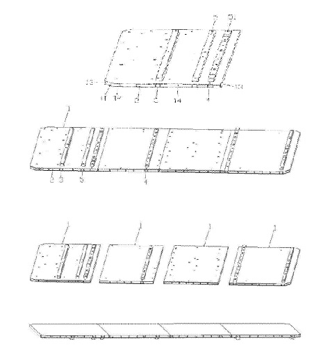
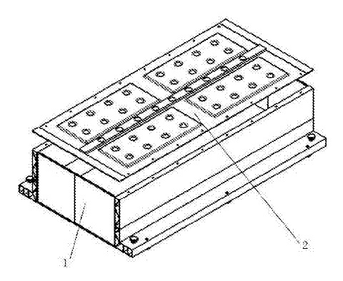
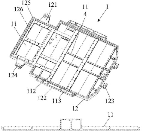
CN209119197 (U) — ALUMINUM PROFILE BATTERY BOX FOR ELECTRIC AUTOMOBILE — Nat New Energy Vehicle Co. Ltd. (China) — The utility model discloses an extruded aluminum profile battery box for an electric automobile, which belongs to the technical field of new energy battery parts and comprises a battery box body, the battery box body is fixedly connected onto the automobile, and the battery box body is made of aluminum materials. Wherein the battery box body comprises a bottom plate and a frame fixedly connected to the periphery of the bottom plate; the bottom plate comprises a first bottom plate, a second bottom plate, a third bottom plate, a fourth bottom plate and a fifth bottom plate which are welded in sequence; the frame comprises a first frame edge arranged at the end part of the first bottom plate; wherein the second frame edges are arranged on the two sides of the first bottom plate respectively, the third frame edges are arranged on the two sides of the second bottom plate respectively, the fourth frame edges are arranged on the two sides of the third bottom plate, the fourth bottom plate and the fifth bottom plate respectively, the fifth frame edge is arranged at the end of the fifth bottom plate, and the first frame edge, the second frame edge, the third frame edge, the fourth frame edge and the fifth frame edge are fixedly connected. The aluminum profile battery box for the electric automobile is reasonable in structure, high in corrosion resistance and convenient to produce and machine, the machining cost is reduced, and the strength and the energy density of the box body are improved.
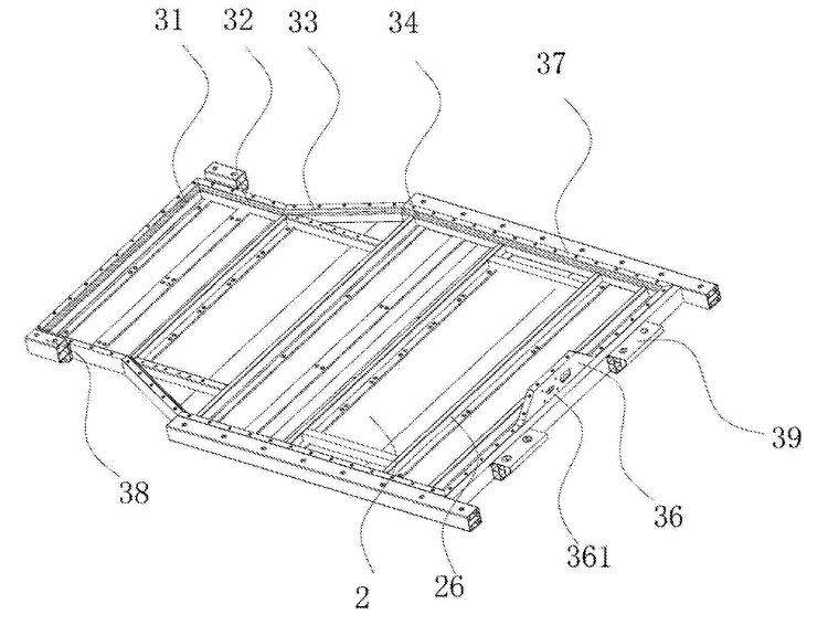
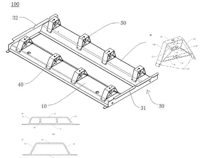
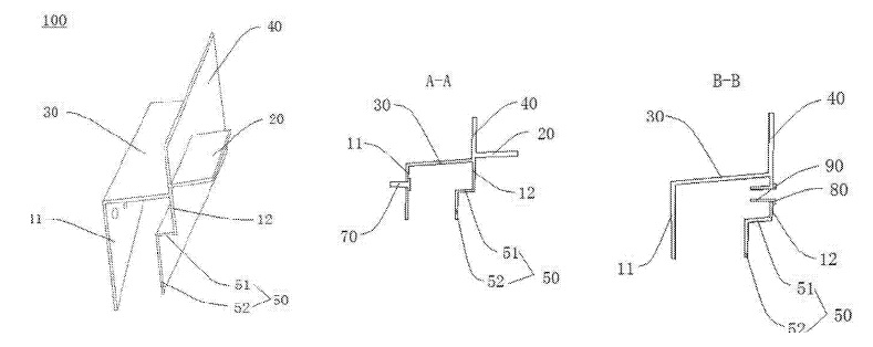
CN208931174 (U) — SEAT MOUNTING STRUCTURE FOR VEHICLE AND VEHICLE WITH SEAT MOUNTING STRUCTURE — Beijing Electric Vehicle Co. Ltd. (China) — The utility model discloses a seat mounting structure for a vehicle and the vehicle with the seat mounting structure. The seat mounting structure comprises a front cross beam, a rear cross beam and supporting brackets, a plurality of seat front mounting brackets are arranged on the front cross beam, a plurality of seat rear mounting brackets are arranged on the rear cross beam, the front cross beam and the rear cross beam extend in the left-right direction of a vehicle, and the front cross beam and the rear cross beam are both fixed to the supporting brackets. The embodiment of the utility model discloses a seat mounting structure for a vehicle. A seat front mounting bracket and a seat rear mounting bracket are arranged; the high accuracy of mounting the seat on the seat mounting structure can be ensured; the seat installation structure is simple in structure and convenient to adjust and install, the seat installation process is simple, the size chain is short, and therefore the installation function size of the seat can be guaranteed, the seat installation structure is made of aluminum extrusions, and it is guaranteed that the seat installation structure is simple, low in weight and high in strength.
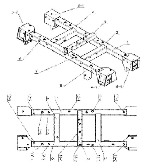
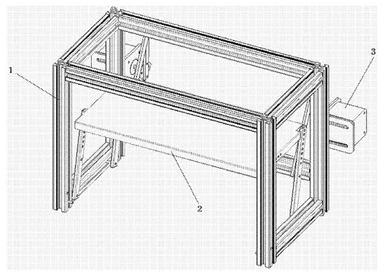
CN208827935 (U) — MOUNTING FRAME AND FRAME ASSEMBLY — Shanghai Maple Automobile Co. and Geely Holding Group Co. Ltd. (China) — The utility model provides a mounting frame and a frame assembly and relates to the field of electric vehicles. The mounting frame comprises a frame body made of aluminum alloy sections, wherein the frame body comprises a front cross beam and a rear cross beam which are parallel to each other and are symmetrically arranged; a middle longitudinal beam is fixed between the front cross beam and the rear cross beam and located on the upper side of the front cross beam and the upper side of the rear cross beam. A left longitudinal beam and a right longitudinal beam are further arranged on the two sides of the middle longitudinal beam respectively and fixed between the front cross beam and the rear cross beam respectively. A lower vertical beam is further perpendicularly and fixedly connected to the lower side of the rear cross beam and located on the right side of the right longitudinal beam. The frame assembly comprises the mounting frame and further comprises a frame, and the mounting frame is connected to the frame in a rivet welding combination mode. The technical problems that a traditional frame device is large and heavy and difficult in weight reduction are solved.
CN208813323 (U) — DOORSILL BEAM FOR VEHICLE AND VEHICLE WITH DOORSILL BEAM — Beijing Electric Vehicle Co. Ltd. (China) — The utility model discloses a doorsill beam for a vehicle and the vehicle with the doorsill beam. The doorsill beam comprises a doorsill beam body, the doorsill beam is an integrally formed aluminum alloy part, and a riveting landing edge is arranged on the surface, facing the interior of the vehicle, of the doorsill beam body. According to the embodiment of the utility model, the threshold beam for the vehicle is an integrally formed aluminum alloy part; the strength of the threshold beam can be guaranteed, the light weight of the threshold beam can also be guaranteed, meanwhile, the development process is simplified, the manufacturing cost of the threshold beam is reduced, the threshold beam is connected with the vehicle body floor through the riveting landing edge, and reliable fixation between the threshold beam and the vehicle body floor can be guaranteed.
CN208646964 (U) — DOUBLE ELECTRIC MOTOR CAR ALUMINUM CHASSIS STRUCTURE — Aipu Vehicle China Co. Ltd. (China) — The utility model relates to a double electric motor car aluminum chassis structure, including two main longitudinal girders and two main beams, the both ends of two main longitudinal girders be equipped with the main beam to it is continuous through the connecting piece, wherein the main longitudinal girder part of extending to both ends be equipped with respectively that the front wheel hangs system installation mechanism and the rear wheel hangs system installation mechanism. The utility model has the advantages of simple structure and reasonable design, convenient to use, aluminum extrusion profile construction intensity is high, can satisfy the strength requirement of chassis stress of traditional steel construction and has higher structural stability and environmental protection.
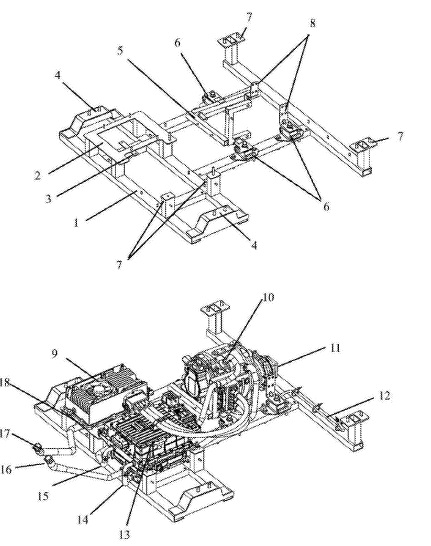
CN208324855 (U) — PURE ELECTRIC VEHICLES’S ALUMINUM ALLOY POWER ASSEMBLY INSTALLATION DEVICE — Zhejiang Hozon New Energy Automobile Co. Ltd. (China) — The utility model discloses a pure electric vehicles aluminum alloy power assembly installation device, including installing support assembly, power assembly frame, suspension assembly, reduction gear installation support assembly before installation device frame body, electrical source controller installation support assembly, electronic pump assembly installing support, the frame behind installation support assembly, the frame. The utility model discloses a pure electric vehicle aluminum alloy power assembly installation device, the part in automobile body lower part position is to motor, MCU and controller isokinetic assembly concentrates the level to arrange, adopts that device is unified to bear the stress, and guarantees a four mounting point even stress on the white automobile body front longitudinal. Simultaneously, replacing the traditional square steel shape with an aluminum alloy replacement achieves the desired light weighting and structural stability.
CN208073062 (U) — HYBRID SKY PARKING PAVILION — University of Chuzou (China) — The utility model discloses a hybrid sky parking pavilion, include aluminum section bar framework and install parking mechanism and the power unit on aluminum section bar framework. The aluminum section bar framework includes a pole setting, four side horizontal poles and three horizontal poles that set up along the horizontal direction along water graphic settings that are set up in edge in four vertical directions, and the parking mechanism includes the parking board and four rocking arms installed on the parking board. The side of the movable mounting in the parking board is passed through to one end of a rocking arm, and the other end of the rocking arm other end passes through a movable mounting on the horizontal pole of second side, while the power unit includes a step motor, electric motor connecting plate, actuating lever, and pull rod. The utility model discloses a parking board which is divided into two-layer parking equipment, with vehicles parked on the upper strata, and the lower floor space can be used for parking vehicles such as bicycles, electric battery cars, and motorcycles.
CN207579805 (U) — ANTICOLLISION CROSSBEAM AND VEHICLE — Kandi Electric Vehicles Shanghai Co. Ltd. and Geely Holding Group Co. Ltd. (China) — The utility model provides an anticollision crossbeam and vehicle and relates to vehicle manufacture. This anticollision crossbeam includes: a crossbeam body and an energy-absorbing box made of an aluminum alloy welded to the crossbeam body. The utility model provides a crossbeam body and the energy-absorbing box welded to the anticollision crossbeam which not only can reduce the weight of the crashproof crossbeam and so promote mileage and energy efficiency. Through the welding process, the manufacture of a die and stamping of sheet workpiece are eliminate, manufacturing costs obviously reduced, and high quality is maintained.
CN207303162 (U) — BATTERY BOX FOR ELECTRIC VEHICLES — Reos Vehicle Tech Suzhou Co. Ltd. (China) — The utility model discloses a battery box for electric vehicles, including the battery box cover plate. Part of the body which is used for the storage battery, the battery upset frame body comprises the welding of a plurality of lapped aluminum alloys in proper order, battery box cover plate includes inner panel and planking, adopts double -deck aluminum alloy punching press to form. The aluminum alloy of the battery upset frame body all utilize aluminum extrusions. The utility model provides a battery box for electric vehicles when guaranteeing that battery box for electric vehicles can install smoothly, in the same direction as the more effective battery that protect the internal portion of battery upset frame, lightens the load, and can also improve the intensity and the rigidity of whole box.
CN207217628 (U) — BATTERY BOX FOR ELECTRIC VEHICLES — Beijing Pride New Energy Battery Co. Ltd. (China) — The utility model relates to an electric automobile technology, and specifically relates to a battery box for electric vehicles. The utility model provides a battery box for electric vehicles, including a case lid and box, the box includes a bottom plate and an aluminum alloy frame. The lower extreme of the frame links to each other with the bottom plate and encloses an upper lid that holds the chamber, and the case lid closes in the open end of the box and the sealed chamber. The box is made of aluminum alloy extrusions, so the weight of the aluminum battery box is much less than that of an equivalent steel body. The aluminum alloy is superior to the steel material as the adherent oxide layer of aluminum protects against corrosion, and its lighter weight with at equal volume further improves battery box energy density.
CN203854752 (U) — DOUBLE-H FLOOR STRUCTURE SPECIAL FOR ALL-ELECTRIC VEHICLES — Henan Suda Electric Automobile Technology Co. Ltd. (China) — The utility model discloses a double-H floor structure special for all-electric vehicles. The double-H floor structure made of aluminum alloy material comprises a front floor. The double-H floor structure is characterized in that reinforcing bars are arranged on the front door, the front floor is fixed on the rear segment of a left longitudinal beam and the rear segment of a right longitudinal beam, the left and right longitudinal beams are arranged on two sides of the bottom of the front floor, a front seat mounting reinforcing beam is disposed on the front floor, a center passage reinforcing plate is disposed on a bottom plate structure along the axis, a floor beam is disposed at the front end of the bottom plate structure, and a center floor front support plate is disposed at the rear end of the bottom plate structure. The double-H floor structure has the advantages of high overall strength, high rigidity, high structural safety, and high bearing capacity; arrangement of a power battery is favored, and the requirement for installation and fixation of the power battery and the requirement of passengers for riding comfort are fully met.
CN203597005 (U) — ALUMINUM ALLOY FRAME FOR ELECTRIC AUTOMOBILE — Loudi Dafenghe Electric Vehicles Co. Ltd. (China) — The utility model provides an aluminum alloy frame for an electric automobile. A main vertical beam made of aluminum alloy irregularly-shaped tubular products is arranged at the center of the bottom of the frame, the two sides of the main vertical beam extend in parallel to form a left side beam and a right side beam, the front end of the main vertical beam is provided with an automobile head assembly, and a seat support is arranged in the middle of the main vertical beam and battery frameworks are formed on the two sides of the seat support. A rear left side frame and a rear right side frame are formed on the tail portion of the main vertical beam. A controller fixing support is formed between the rear left side frame and the rear right side frame. The aluminum alloy frame for the electric automobile has the advantages that the main vertical beam is of the aluminum alloy irregularly-shaped tubular structure and is formed through an extrusion molding technology, therefore, the strength is high and machining is convenient; the side beams are arranged in a parallel extension mode and the other parts are formed after being placed at the corresponding positions; after the aluminum alloy structure is adopted, the weight of the finished automobile is greatly lowered, the actual service life of the electric automobile is greatly prolonged, electricity consumption and production cost are lowered, the service life of the electric automobile is prolonged and the aluminum alloy frame is suitable for mass production and finished automobile weight reduction.