By Philipp Hettich, Laubinger + Rickmann GmbH & Co. KG,
and Martin Hartlieb, Viami International Inc.
Extrusions are increasingly used for complex parts in the transportation industry. They allow for very complex cross-sectional shapes and, therefore, integration of different parts and functions (like cooling channels) into a single extruded profile. The rapidly increasing electrification of vehicles is expected to boost the market for extrusions even more, with typical applications in vehicles being (sub)structures, chassis, closures, electric motor housings, and battery housings. These new extruded parts, such as long, wide, and complex profiles for battery trays, require tight tolerances and high mechanical properties to improve their crashworthiness. As a result, these parts are presenting new challenges for extruders. In order to achieve the required properties, extruders need to implement heat treatment and rapid quenching, which can easily distort the extruded profile.
Conventional straightening processes like stretching are no longer sufficient to master those distortions. This is because manual or semi-automatic straightening of such large and complex profiles is time consuming and costly and can also create other problems in the parts, contributing to higher scrap rates. Processes like hydroforming can also be used to straighten the part, but are not economical for just straightening a profile (unless there is additional need for forming the part). Automatic, intelligent straightening systems that adapt to process parameters and the specific needs of the part through self-learning artificial intelligence (AI) algorithms are, therefore, becoming the ideal solution for extruders that want to enable the economical production of complex profiles with high mechanical properties and tight tolerances.
Distortion in Extrusions
In aluminum processing, distortion typically occurs at various points of the extrusion process, including during the forming process (at the extrusion press, at the die exit, and during press quenching), during heat treatment (when it is hot and therefore soft), and especially during quenching. It also occurs in downstream processes like sawing, machining, and welding of assemblies.
Rapid and efficient press quenching (in 6000 series alloys) or after solution heat treatment (in the case of some 2000 and 7000 series alloys) is critical for achieving high mechanical properties, as it determines how many hardening elements are retained in solid solution. This is the main cause for distortion, especially if the quench rate along the profile is not constant due to irregular water flow and/or part geometry. There is an optimum quench window that provides the best compromise between desired properties and allowable distortion.1 However, it is sometimes very difficult to find this suitable compromise, because the requirements are simply too high. As customers are unlikely to compromise on properties or tolerances, a solution has to be found to manage the distortions.
In order to control and minimize distortions, technical advancements and improvements have been made with respect to simulation of the process (and the part), improved heat treatment furnaces (homogeneity, heating rates, etc.), proper racking/support during heat treatment, and new quenching techniques (quench media, temperature, and agitation). However, even all of these new technologies are still not sufficient to meet all properties and tolerance requirements for complex profiles. Therefore, the latest innovations in straightening of extruded profiles are now being increasingly implemented in extrusion and assembly plants.
Most profiles have always been straightened (or “calibrated,” as some extruders call it) in some way after the extrusion process, in a process typically called stretching. After the runout and cooling table, the profiles are moved to a stretcher, where they are straightened by stretching them between 1-3%.2 This is no longer always sufficient, and thus, much more complex straightening is required.
Basics of Straightening
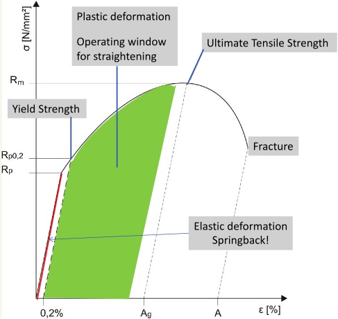
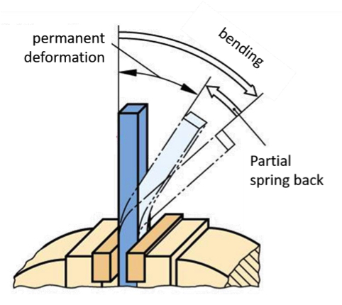
Straightening is the correction of distortion through plastic deformation of a part in order to bring it back into its intended shape. Physically, this means that a section of a part is pushed beyond its yield strength (beyond elastic deformation), but below its tensile strength (Figure 1). Achieving the proper straightened shape involves elastic spring back (Figure 2), which essentially means that the profile is over straightened, or bent more than necessary, after which it jumps back via elastic spring back to achieve the right shape and tolerance. The amount of spring back is not always identical, as it depends on the exact forming process of the part. Therefore, this process sometimes has to be repeated several times.
For manual straightening, a part is 3D scanned or otherwise measured. If the operator notices distortion, the part is mechanically brought into the desired shape and tolerance and then checked again. This often has to be repeated several times, which makes this process time consuming and costly. It also requires considerable skill from the operator to avoid damaging the part.
Depending on the individual specification and type of distortion, different straightening techniques may be applied, including global (overall) straightening, local straightening, datum point straightening, and flange straightening (roller straightening). Global straightening is important to correct specific general distortions of the part, like torsion or a complete bending of the entire part. In contrast, local straightening mostly refers to joining surfaces, sealing surfaces, or function-critical areas where a very specific straightening stroke is required.
Datum point straightening refers to a special technique that achieves an overall effect on the part by applying local forces. In this technique, the area around the datum point (never the datum point itself) is locally deformed with the aim of changing the datum point’s relative position to other measuring points. This mixed form is especially important when it is more effective to manipulate one datum point instead of orienting many measuring points at one datum point.
To correct waviness of flanges and wings or to adjust an angle between the main body and the flanges, roller straightening can be an additional step. However, one should always consider what can already be achieved when straightening the main body of the part, as the flanges usually follow the main body.
Straightening Extruded Profiles
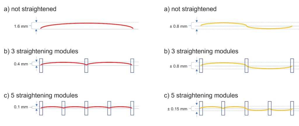
In long profiles, distortion does not only happen in one section and one direction, so it often has to be straightened progressively in a series of incremental bending, rotating, and pressing operations in several shorter segments. During these operations, the part needs to be well supported to avoid buckling. Each of these steps also risks causing a new distortion in other sections of the profile, which makes it obvious that this is a complex process that requires a lot of precision and adjustments. Using the right segmentation of the profile can be vital in achieving the desired straightening (Figure 3).
Despite all available material data and simulation capabilities, straightening still requires a significant amount of trial and optimization with real parts. This is because the full range of possible distortions of the part and its behavior need to be known. Only then, in combination with the correct segmentation and an ideal combination of straightening techniques, can the perfect straightening stroke be achieved, in which all incremental individual steps are executed simultaneously in order to obtain a part within the tolerance specifications in minimum cycle time with one straightening stroke.
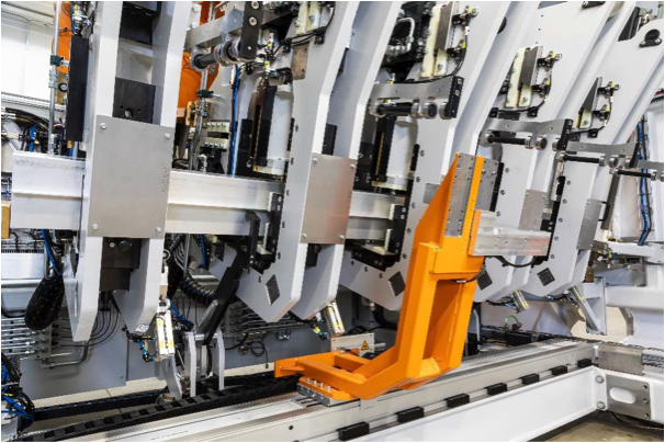
Automatic Straightening Systems
Intelligent, automatic straightening systems (Figure 4) are highly complex and require significant engineering and investment, but they can be well worth it. They use synchronized forces at the part where and when they are needed to ensure local and overall results. The system will immediately counteract an unwanted deformation in an area of the profile (resulting from straightening a different area) by applying a counterforce in the right location. This means that the system is working with the part and not against it. These systems can learn and optimize the straightening process by themselves, achieving results otherwise impossible to obtain.
With regard to the design of these highly automated measuring and straightening systems, a distinction can be made between flexible systems for multiple profile types and part specific large-scale production systems. The decisive factor for flexible systems is a short set-up time, as well as the suitability of the systems to correctly detect the part position even with changing geometry and positioning and, ultimately, the ability to apply the force at the correct points. In this case, the investment is often spread over a larger amount of product types, providing faster amortization of the investment (often within 1-200,000 profiles).
The basic procedure is common for both manual and automated types of straightening systems (flexible and specific large-scale systems). The part is measured, then straightened and then again measured to determine the achieved result. In an automated system, the datum points of the part are first determined by measurement. This avoids measurement errors due to damage or elastic or localized plastic deformation on datum points. For these reasons, the datum points should never serve as a support surface. The measurement itself can either be tactile (providing speed and accuracy), with lasers on several surfaces in parallel (providing flexibility for different profile types), or a combination of both.
Based on this determination of the part’s position in the space, the other measured values of the part surface are mathematically transformed to obtain a complete virtual image of the part and its distortions in a fraction of a second. Based on this virtual model, the machine decides what straightening functions (units) will be used and to what degree. A 3D straightening system has three axes for the process: Y, Z, and torsion about the X axis. Straightening along each axis is controlled by distance rather than force. In combination with repeated (online) measurement of the effect, this allows determining the plastic and elastic components of the applied deformation.
After each straightening cycle (measurement, straightening, and measurement), the software creates a record for all straightening points and parameters, including the combination of straightening units, straightening path, number and effect of each stroke, etc. This enables the extruder to draw additional conclusions about the manufacturing process with respect to its impact on tolerances of the part, but also regarding changes of the material characteristics (change in properties, residual stresses, etc.).
The initial cycle time and capacity of the system needs to be calculated and the system is designed and adjusted from the beginning, so that ideally one single piece of equipment can handle the required volumes during the entire project. Unlike manual straightening, the automated equipment cannot easily be expanded after it is built and installed. Typical cycle times are in the range of 30-60 seconds for part specific systems and 70-140 seconds for a flexible system, and such systems only require a single operator for one to two systems.
In the case of unique part identification, the initial measurement can also be decoupled from the straightening station to achieve minimum cycle times. This enables pre-selection of the parts to be straightened and avoids overloading the straightening system with parts that already meet the tolerance requirements.
The system can be integrated into production lines and parts loaded and unloaded automatically (e.g. with robots), so that an operator is only required for setup of a new profile type. Compared with a manual or semi-automatic straightening system, fully automated systems can significantly reduce required floor space and cause very little downtime. They distinguish themselves with extreme precision, quality, and repeatability. Without automated straightening systems, many complex profiles could not be produced competitively with the standard aluminum extrusion process.
An automated straightening machine has been in use at Hammerer Aluminium Industries (HAI) in Austria, where the company produces parts for the automotive and other industries. Figure 5 shows an approximately 3 m (almost 10 ft) long EV sill extrusion that forms both the longitudinal beam of the electric vehicle, as well as the side member of the battery housing. This makes this structural extrusion crash relevant (high requirements on mechanical properties) and results in very high tolerance requirements — beyond the standard capabilities of extrusions. After the automatic straightening process, the part is within a 1 mm tolerance over the entire length. By comparison, a part made with conventional methods would typically have extrusion tolerances at about 0.7 mm per meter of the profile length, which would mean a tolerance within 2.1 mm (over a 3 m length).

Conclusion
Aluminum extrusions have seen growth in the transportation industry over the decades and this growth is now accelerating with the electrification of vehicles. New parts like battery trays can ideally be made with large and complex extrusions. In order to meet both properties and tolerance targets, profiles are increasingly requiring extensive straightening operations. As distortions can vary significantly from part to part and manual or semi-automatic straightening can be very difficult, time consuming, and costly, new automatic straightening systems have been developed and their implementation in the extrusion industry is increasing. These intelligent systems are using AI to adapt and adjust to varying distortions and can even alert the operator if something in the process is changing that requires attention and fixing. With that, extruders are able to meet both property requirements and very tight tolerance requirements in large extruded profiles, which allows them to competitively offer and produce new complex extruded parts for components like battery trays and enter the rapidly growing automotive market with high value-added aluminum extruded products.
References
- Bikass, S., et al., “Distortion Mechanisms Due to the Cooling Process in Aluminum Extrusion,” Proceedings of the Tenth International Extrusion Technology Seminar & Exposition (ET ‘12), July 2012.
- Fourmann, Jerome, “Defects Affecting Extrusion: Stretcher Strains,” Light Metal Age, April 2018, pp. 14-16.
Editor’s Note: This article first appeared in the April 2021 issue of Light Metal Age. To receive the current issue, please subscribe.