By Matthew Cortelli, P.E., Ramboll.
As new secondary aluminum plants are not mass produced, it is pertinent to utilize the lessons learned from previous projects and apply best available technology (BAT) to the next one, so that aluminum remelt facilities can benefit from the continuous improvement process. Ideally, the secondary aluminum producer involves operations personnel at the earliest stages of the project to ensure they have a personal stake in the final product as well as provide their insights and lessons learned from their previous experiences. It is also important to keep the core team intact, if possible, throughout the life cycle of the project.
After any project, it is important to create a “Lessons Learned” document to record the successes and challenges encountered during a project. Lessons learned are crucial, as they facilitate the transfer of knowledge and insights from one project to another, ensuring continuous improvement and learning. It is important to take the time and assemble the key team members at the close of the project to review what went well and what would be done differently, if it were to be done over again.
This article will focus on the lessons learned during the engineering and design phase of the development of secondary aluminum remelters, as well as modifications and modernizations made to existing facilities, based on over thirty years of experience in the industry. It will not address project execution, construction management, start-up, or commissioning activities although lessons learned here are as equally important.
Secondary Facility Design
General Casting Center Arrangement
Modeling of the casting center using casting speed, cast length, melt rate, and other tasks and parameters will determine what equipment will be needed for a given data plate throughput and how many casts are expected in a 24-hour period. In an ideal world, transfer and casting launders would be as short in length as practical to minimize temperature loss, tending and maintenance demands, and cost. However, in so doing, casting equipment can become very cramped making it challenging to operate, maintain, and drain.
When planning the casting center, the engineer is tasked with trying to fit in a rod feeder, degasser, ceramic foam filter (CFF), automated dams, molten metal level control equipment, jib cranes, and drain/drip pans in this area along with other ancillary equipment. As casting technology is becoming more “hands free” in approach, the remaining “hands on” tasks need to be made as safe as possible—avoiding pinch points as well as potential damage to equipment. For example, attention needs to be paid to how run-around scrap and drain pans are brought back to the scrap area for remelting. Ideally, the traffic patterns are indoors, so that operators are not exposed to inclement weather. Making the between-cast tasks easier and safer to accomplish will reduce the turnaround time on the casting center.
The Casting Center Control Room should be conveniently located with good visibility of the casting area but far enough away that any elevated product from the overhead casting bay crane won’t accidently contact the room or the room is adequately protected from contact. A combination tepid water safety shower/eye wash station is recommended in the casting area.
Also important to note: the casting pit concrete and any associated steel casting equipment needs to be coated with an approved epoxy safety coating, which creates a barrier between the wet substrate and molten aluminum to reduce the risk of a molten aluminum explosion.
Access to the Regenerative Burner Cassettes
These are common on reverberatory aluminum melting furnaces, but care needs to be given on accessing the burner cassettes. Some facilities are now utilizing third-party contractors for removing, cleaning, and replacing the burner media. However, it is a widespread practice to have spare burner cassettes at the ready that can be quickly exchanged. For a new facility, there is no excuse not to allow for adequate room to perform this function.
Sometimes creative material handling solutions are necessary (such as an air sled) to perform this task, but since the burner cassettes can be large, heavy, and hot, it is important that this operation be done as safely as possible—so the more room the better. This is also a great application for using refractory, steel, or aluminum plates in front of the furnace doors to protect the concrete from molten metal spills, which easily damage exposed concrete.
Access to the Electromagnetic Stirrer (EMS)
These are installed and operated in the most extreme conditions, routinely under the furnace. Provisions need to be designed into the furnace foundation not only for supporting the EMS but also for its removal and replacement. An access pit adjacent to the furnace in which the EMS can be transferred to and then pulled out of instead of having to work under a fully tilted furnace (mechanically braced, of course) is a safer approach.
Homogenizing/Log Handling Systems
These are typically comprised of highly automated systems that are free of operators. The entire area should be surrounded by a safety fence with strategic locations for maintenance access gates, including access for forklifts or mobile cranes. Policies need to be in place for Lock Out-Tag Out (LOTO) when access by operators or maintenance is required. This can be mapped out to make sure a module of the system can be isolated, ensuring that access does not impact the entire operation. Of note here is that, if possible, it is always best to have the furnace stacks and cooler inlet/outlet ducts hidden from view of the public approach side of the plant and away from residential areas, because these can be significant sources of noise. This can also be done with 90-degree elbows at the terminus of the stacks, which can be rotated and pointed away from sensitive areas.
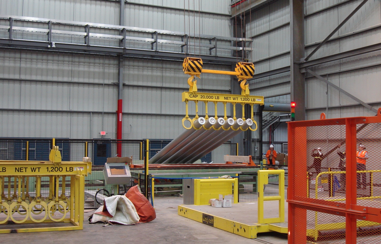
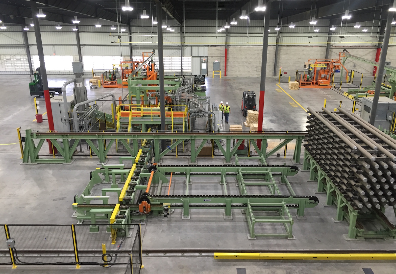
Sawing, Packing, and Finished Goods Storage
This is typically where personnel are stationed, operating the saw and removing product from the system (Figure 1). Indoor finished goods storage is typically located here, so an area of so many days of production is determined and designed in. This minimizes the travel distance from the saw to storage, thereby making for a more efficient and safe process. Loading trucks can be used inside the building with a drive through, loading docks, or an overhead bridge crane. Outdoor loading of trucks can be accomplished with mobile dock ramps, permanent combination truck well/dock, or from grade level with approach to the side. If rail service is nearby, a rail spur with dock can be added for shipping or receiving.
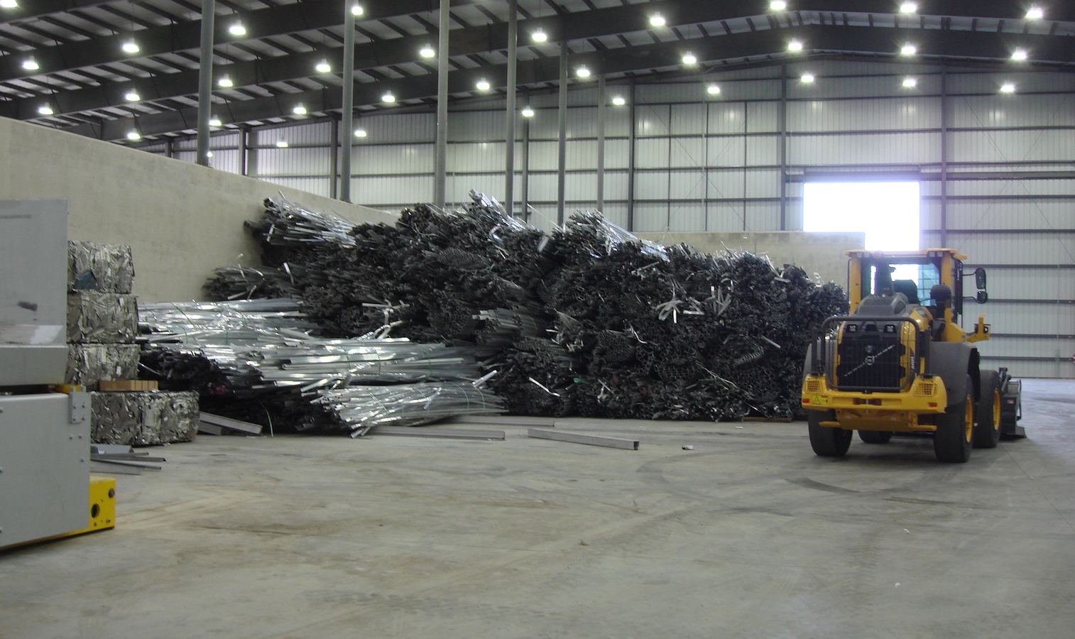
Covered Scrap Storage
In light of safety and avoiding moisture ending up in the melting furnace, there has been an industry trend towards covering the scrap storage area to protect the scrap from stormwater (Figure 2). Determining the number of days required for covered scrap storage and the average scrap density will dictate the overall size of the area.
Scrap bins can be made using heavily reinforced cast-in-place concrete, fabricated steel partitions, or portable concrete bin blocks, however, these typically require a substantial concrete footing under them. Scrap bin heights can be optimized based upon the type of scrap being placed in the bin. If trucks will be tilting their trailers to unload the extrusion scrap, plan for the necessary overhead clearance in the area. Provisions for an overhead door/opening in the building that allows the truck to pull out with the trailer fully raised is advised. Overhead door widths should be designed to accommodate long scrap that may be coming in from outside via wheel loaders.
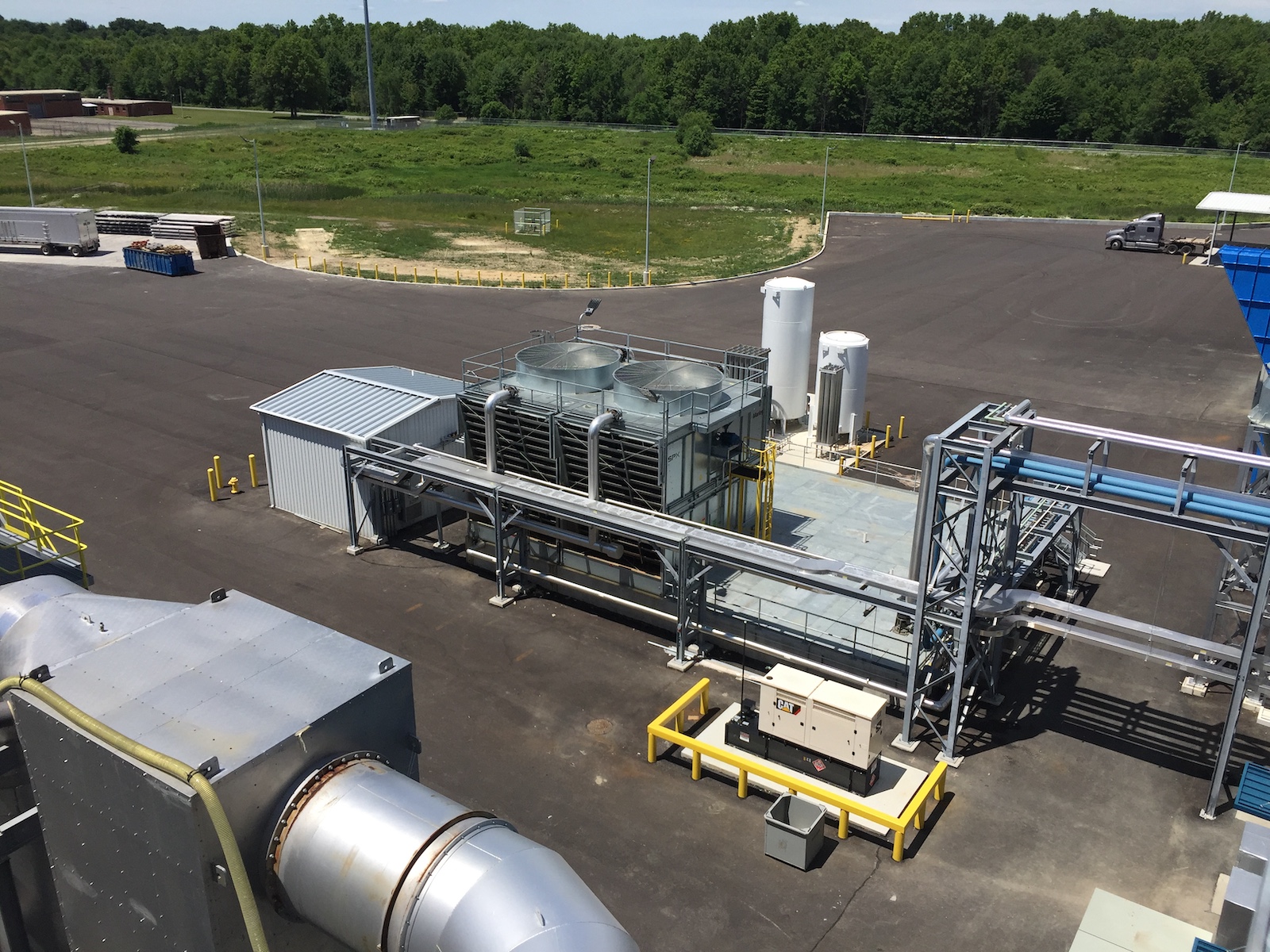
Yard Equipment
Ancillary equipment used to support production—such as baghouses, cooling towers, emergency water towers (if not inside the casthouse), water treatment building, process gases (such as argon, oxygen, and chlorine), emergency diesel generator, diesel fuel storage tank, and outside scrap storage, to name a few—are located on the “back side” of the plant, typically away from view of the primary road, administration, and residential areas, if possible (Figure 3). This is considered the “dirty” side of the plant, and the preference is to keep it hidden. Be sure that service (or emergency) vehicle access is not impeded and ideally does not interfere with production vehicle traffic. Space around these areas is also required for maintenance, and it is beneficial to have the baghouses distanced from the building in the unfortunate event of a fire. Fire protection for baghouses is advisable. Combination tepid water safety shower/eye wash stations are recommended in the water treatment building and at baghouses, especially if lime injection is present.
Production Support Areas
Do not forget about the necessary support areas including the mold maintenance shop, warehouse, general maintenance shop, weld shop, wash area for mobile equipment, laboratory, locker rooms, restrooms, break rooms, first aid station, conference rooms, and offices. Some secondary producers like these spaces integrated into the plant and others like some of the areas remote from production. It is imperative to take the time and program discussions with all parties, as there are usually many opinions associated with these areas. Care must also be exercised with regards to state and local building codes as it relates to life safety.
Site and Utilities
Site Conditions
Engaging a reputable engineering firm is key at the start of the project, as site conditions will dictate building and equipment foundation design. Soil conditions, seismic design category, and geographical location all drive these designs. Be aware of other influences, such as water features, topography, and endangered/protected species of animals or plants.
Space is Your Friend
There is a tendency to design pre-engineered metal buildings (PEMB) surrounding process equipment to be as compact as possible for fear of spending money on unnecessary building volume. If not that, when the project schedule dictates that a building envelope is to be defined based upon preliminary equipment supplier information, a factor of safety should be included in the footprint as space allocation tends to be overly optimistic in the initial stages of the facility design. This often results in the intersection of multiple roof lines and building walls, resulting in not only an overly complex structure and foundation design, but also impediments for maintenance.
Simplifying the structure will make the erection process quicker and less prone to leaks. It will also provide the operations with enough space for maintenance to perform their jobs more safely and will more likely prevent problems in the first place, if there is adequate room for forklifts, rigging, and mobile cranes. Be mindful that overhead clearance for mobile cranes is necessary during the initial erection of the equipment as well.
When building the PEMB, allow for generous “windows” between the purlins (horizontal structural members for the roof) for anticipated roof penetrations and between the girts (horizontal structural members attached to columns that support wall paneling) for anticipated wall penetrations. This will ensure that rework is not required later in the field to accommodate minor adjustments to size or location. Provide ample space above the casthouse crane rails for the overhead bridge crane and necessary headroom for rigging during installation.
Utility Distribution
Related to space allocation, provisions must be accounted for utility distribution, especially where it runs overhead on utility racks that support piping and cable tray. These are typically routed along the perimeter of the facility and are preferred over embedding pipe and conduit in or under the concrete floor for their accessibility and ease of expansion later. This space must be accounted for early in the design process to ensure that it does not create obstacles with equipment or impede overhead bridge crane hook travel limits. Adequate isolation valves should be provided, so that if a piece of equipment must be taken offline for maintenance, it can be isolated from the utilities without impacting other production equipment. For the discharge of emergency water from an elevated tank, specify a circuit setter valve in lieu of an orifice plate on the discharge side, as it can be adjusted during commissioning and then locked in.
Network and Structured Wiring Needs
These details need to be defined early in the project to ensure that the proper software and hardware is incorporated into the ever-more sophisticated equipment that makes up a secondary aluminum remelter facility. There needs to be familiarity with terms like Supervisory Control and Data Acquisition (SCADA); Industry 4.0, 5.0, and even 6.0; Internet of Things (IOT); and artificial intelligence (AI). Network racks should be located within the physical limits of the communication cabling or higher quality cabling specified, if intermediate racks are not an option. Secure remote access demands are increasing where key elements of the overall process can be monitored from a wireless tablet or even a smartphone. Video surveillance has also advanced tremendously, and its application has gone beyond general security to include observing the interior of the furnaces, casting center, and even below-the-hook (BTH) lifting devices. There really is no limit to where a camera can be placed for continuous remote monitoring.
Be Kind to Electrical Gear
As equipment gets more sophisticated and dependent upon electricity, it is a sound approach to place electrical gear in dedicated protected electrical rooms that are climate controlled. Mechanical abuse, temperature, and moisture are not friendly to delicate electrical components, so using concrete masonry unit (CMU) construction, dedicated HVAC, and housekeeping pads will dramatically improve the longevity of this equipment. Ample LED lighting and a formal arc-flash analysis will make maintenance safer as well. Double steel doors with a removable transom and/or an overhead door will allow for easier access when larger gear must be removed and replaced. Try to keep this on the ground floor instead of having to climb stairs to access this equipment. It is also important to allow for future expansion—just as 25% excess capacity is specified in the electrical cabinets, the same should be applied to the room the cabinets are being installed in. Plan for the clear height to appropriately accommodate the top-entry cable tray and any HVAC ductwork.
Be Practical with Mechanical Equipment
Similar to the electrical gear, it often makes sense to have the mechanical equipment housed in a protected central room. Air compressors, hydraulic power units (utilizing fire retardant fluid of course), casting pit utility stands, casting pit water vapor extraction fan (be careful not to refer to this as a steam extraction fan, because mechanical engineers can misinterpret this for high-pressure steam), and so on can be conveniently located in a dedicated room, which is arranged to provide adequate access around each piece of equipment for maintenance. Be mindful whether something large must be removed and replaced and allow space for a mobile compressor to tie into the compressed air system if a spare air compressor is not already present. If the air compressor has large consumers that are quite remote, additional air receivers can be distributed throughout the facility as needed. Typically, these mechanical rooms do not need to be air-conditioned, but forced-air ventilation should be utilized, as they can get hot.
Planning Considerations
Safety
Erector, operator, maintenance, and visitor safety should be the primary focus during project planning and integrated into the engineering and design phase of the new casthouse. Planning the product, operator, maintenance, and visitor pathways into the layout will impact the overall equipment general arrangement. These clearances need to be accounted for, because they will increase the footprint.
Sustainability
This is often related to the environment and the impacts industry may have on climate change, both positive and negative. The goal should be to design a secondary aluminum remelter that contributes to a more sustainable society. Many may think that the fact the aluminum is being recycled is enough, but it goes deeper than this; methods should be considered that will reduce greenhouse gas emissions and decrease the use and/or disposal of hazardous materials, the amount of waste sent to landfills, and consumption of less water or other natural resources. The team may collaborate on a sustainability design review as a separate effort from the project. The review would be aimed at jointly identifying opportunities for additional benefits, including those related to advancing a NetZero strategy, reducing costs, improving business reputation, and mitigating climate risk.
Communication
When collaborating with secondary aluminum producers and equipment suppliers from around the world, it’s important to be mindful that English may not be their first language, and they also may not be in the same time zone. A wonderful way to harbor cooperation is to be mindful of other team member’s locations, language challenges, holidays, etc. Communication with these sensitivities at the front of mind go a long way in fostering an environment of open collaboration and teamwork. With video conferencing tools what they are today, this has made effective communication so much easier. Schedule regular meetings to stay ahead of design parameter requirements, technical issues, deliverables, and schedule.
Conclusion
When asked which of his Super Bowl rings was his favorite, former professional football quarterback Tom Brady answered, “The next one.” This is an excellent mindset to carry into the design and engineering of secondary aluminum projects, and incorporating lessons learned from previous projects is a key part of this continuous improvement process. The advice covered in this article by no means represents a complete list. However, it does highlight some of the primary lessons learned over 30 years working as a consulting engineer in the industry, catering to the secondary aluminum remelting sector and specifically with new greenfield casthouse projects. While many of these points may seem obvious now, they were invaluable lessons learned over time. There will be more lessons to be learned in the future, and it is always exciting to be given the opportunity to apply them to the next “best” project.
Editor’s Note: This article first appeared in the August 2025 issue of Light Metal Age. To receive the current issue, please subscribe.